From the First Triangle to an Error-Correcting
Lattice: Simulations of a Growing Bell-Pair Network
Raghu Kulkarni
SSMTheory Group, IDrive Inc., Calabasas, CA 91302, USA
raghu@idrive.com
Abstract
The Selection-Stitch Model (SSM) treats space as a network of Bell pairs that grows into a
face-centered cubic (FCC) crystal. We first propose what came before growth: a state with no
space, time or energy ledger; persistence as a foundational postulate (“what exists is what can
persist”), under which random entanglements survive only as checked bonds of one length, and
which we prove excludes classical probability theory given two stated premises, though it does
not single out quantum theory; and a first triangle of bonds, which we prove is, with one qubit
per bond, the smallest network whose node and loop checks detect every error on its bonds.
From that seed, stitch extends triangles within their plane and lift places nodes above them.
In 696 simulations of up to 10
6
nodes, about 98% of interior nodes end in FCC order. The
stacking is forced: stitch reflects a corner through the opposite edge’s midpoint, and FCC is the
only close-packed stacking closed under this reflection. Remnant nodes that settle on a front
growing one way are never trapped in tetrahedral voids pointing against growth. Each bond is
a Bell pair, and we show that one parity check per node, made deterministic by measurement
and local repair, turns the Bell-pair network into a code state with one qubit per bond. Its
entanglement entropy obeys an area law, with a coefficient 2.5–6% below ideal FCC because of
defects; the node checks add a constant −ln 2. The weight-12 FCC stabilizer code can be built
on any grown graph, and its checks always commute. At a 5% bond tolerance, 96% of interior
nodes carry the full code structure (89% counting all defects); the 0.15% of interior bonds that
escape every X check give the grown code distance 1 where they occur. In patches grown one
way, twin boundaries remove up to 40% of X checks near the base, and the code heals as one
twin variant takes over.
Keywords: Bell pairs; GHZ state; foundations of quantum theory; entanglement area law;
stabilizer codes; quantum error correction; face-centered cubic; crystal growth; discrete space;
Selection-Stitch Model
1 Introduction
The idea that space is built from entanglement has a long history [1]. The Selection-Stitch Model
(SSM) gives it a concrete form. It proposes that space is a discrete network that crystallizes into
the face-centered cubic (FCC) lattice [2, 3]. Its nodes are joined by bonds of a single length L,
which the SSM identifies with entangled (Bell) pairs. Two operators grow the network. Stitch
adds a node in the plane of an existing triangle. Lift adds a node above or below a triangle, at
the apex of a regular tetrahedron. FCC and hexagonal close packing (hcp) both reach the kissing
number K = 12 and the Kepler packing bound [4]. Packing alone does not decide between them.
For hard spheres the two differ in free energy by only about 10
−3
kT per particle [5], and grown
crystals often show random stacking [6]. This paper shows why the SSM rules select FCC.
Far from the point where growth began, a region of the crystal grows in nearly one direction.
We call such a region a patch. Its growth front is flat on a local scale and moves one way. In
FCC each node sits between two kinds of tetrahedral void, whose tips point in opposite directions
along a stacking axis. In a patch these two kinds differ: one points along the growth direction
1
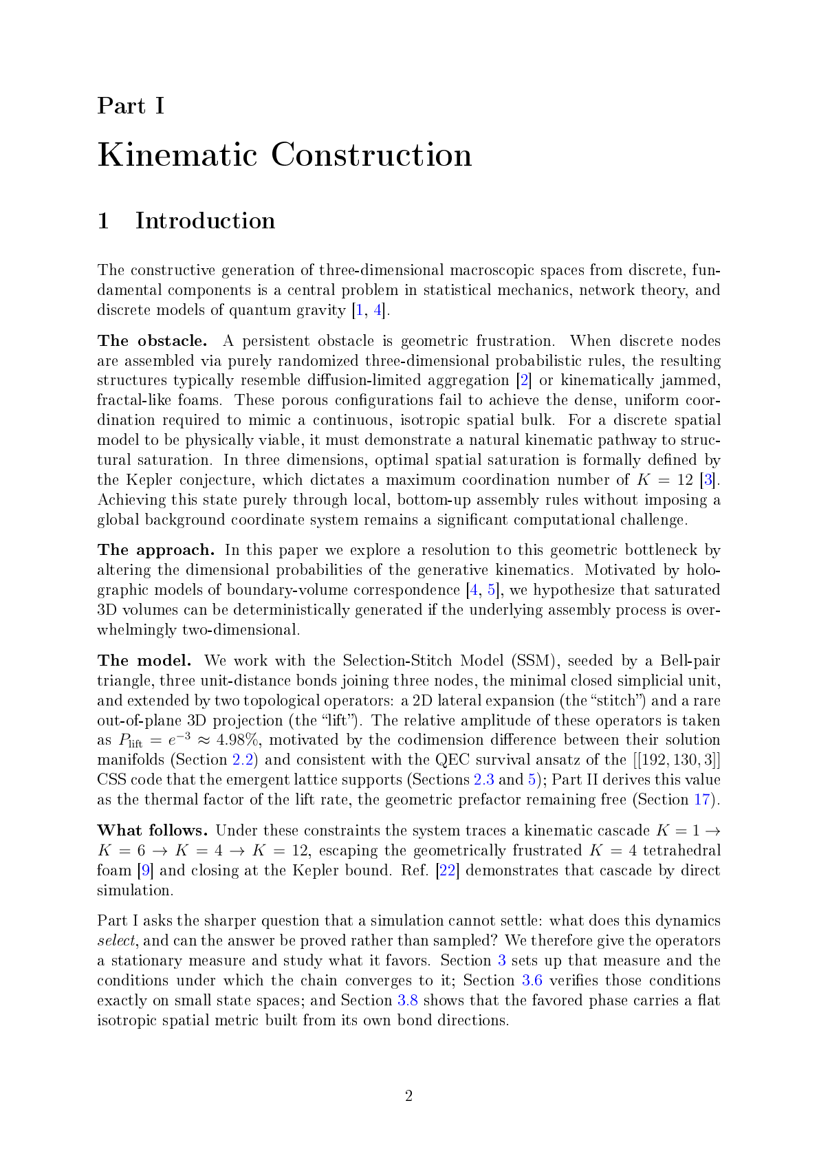
ˆg, and the other points against it. In the SSM, a remnant node left from an earlier disordered
phase (a K = 4 phase in Ref. [2]) and trapped in a tetrahedral void is a baryon, and the two void
orientations correspond to matter and antimatter [2]. Ref. [2] attributes the observed excess of
matter to a local excess of one orientation. Suppose remnants that settle on the growing surface
could be trapped in only one kind of void. Then a patch would hold matter but no antimatter.
Relation to previous work. Ref. [2] reported a smaller simulation of the same rules. It
reached a few thousand nodes and judged structure by coordination number. This paper extends
it in scale and in structural detail. It also adds simulations of patches, modeled as periodic slabs
grown upward from a complete flat sheet. Where our results differ from [2], we say so in place.
We first propose what existed before the seed, why, under two stated premises, they cannot
be classical, why the seed is a triangle, and how random entanglement, kept only where it forms
checked bonds of one length, both creates and maintains space. The growth rules turn out to
apply this principle node by node. We then ask seven questions. Do the rules produce FCC,
and not only 12-fold coordination? What sets the lift rate? How does a patch grow? Is the void
population biased along the growth direction? Where are remnant nodes trapped? Why is the
stacking ABC? And what quantum structure does the grown network carry? The growth itself
is classical geometry. Bonds are distance constraints, and no quantum state is evolved. But if
every bond is a Bell pair, the grown graph fixes a quantum state. Its entanglement, and the FCC
stabilizer code of Ref. [7] built on it, can then be measured directly on the simulated networks.
Section 2 proposes where the first triangle comes from. Section 3 states the model, and Section 4
derives the lift rate. Section 5 gives the methods. Section 6 covers growth from a seed, and Section 7
covers patches. Section 8 measures the quantum structure of the grown networks. Section 9 tests
robustness, Section 10 discusses the results, and Section 11 concludes. Appendix A shows why
the unit-bond condition is needed, and Appendix B compares the code with that of Ref. [2].
Two interactive 3D views go with the paper and can be read alongside it. A growth viewer
replays both kinds of growth node by node, using the same rules and parameters as this paper:
https://raghu91302.github.io/ssmtheory/lattice_growth.html. A second view shows, step
by step, how a new sheet starts at a step edge: https://raghu91302.github.io/ssmtheory/
step_edge_sheet.html.
2 Before the seed: where the first triangle comes from
Every cluster in this paper grows from a three-node triangle, as in Ref. [2]; the patches of Section 7
stand for regions far from that seed. The growth rules say what happens after that triangle exists.
They do not say what came before it, why it is a triangle, or why the rules are quantum. This
section proposes answers. It is a proposal about initial conditions, in the tradition of Refs. [8, 9],
and it is kept apart from the results. Its core about the triangle is exact. A table at the end of the
section lists which claims are proved and which are proposed. No result elsewhere in the paper
depends on this section.
2.1 What existed before the triangle
Before the first bond there is no lattice. In the SSM, distance is a count of bonds, and a clock
is a cycle of checks on bonds. So before the first bond there is no distance, no volume and no
time. The questions usually asked of an initial state do not apply. Density is mass per volume,
and there is no volume, so the state was neither dense nor dilute. “Point-like” and “infinite” are
lattice words. The state had no size.
What did exist is a set of degrees of freedom with no position: two-level systems defined only
by their algebra. We call them proto-qubits. A proto-qubit is not a particle, since particles are
defects of the finished lattice [2], and it has no location, since location is a lattice property. It
becomes the located qubit of the code [7] once a bond gives it a place.
2
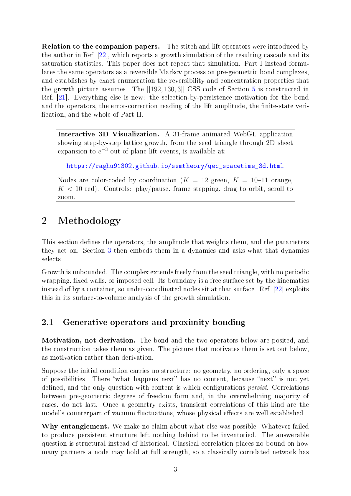
The SSM describes a black hole in the same terms: a region with no lattice and no bonds,
which from inside is an inert code space with no clock [10]. The state before the first triangle is
that interior condition with no exterior. The identity is of condition, not of object. A black hole
has entropy and mass because it has a boundary, where its bonds are counted. The state before
the triangle had no boundary, and so no entropy and no mass.
The state also needs no energy budget. Energy conservation follows from time-translation
symmetry, and there is no time before the first clock. So there is no ledger to draw on, and the
question of what energy built the lattice has no meaning there. Entanglement itself has no fixed
energy cost: entangled and product states can have the same energy, and an isolated entangled state
persists at no cost under unitary evolution. This is a discrete form of the zero-energy argument
of Tryon [9]: no positive and negative energies need to cancel, because there is no account until
there is a lattice to keep it.
2.2 What can exist there: the persistence postulate
Asking what chose the laws of physics seems to start a regress: every selecting law needs its own
selector. The SSM starts instead from one postulate:
What exists is what can persist. What cannot persist cannot become part of an expe-
rienced or observable universe.
We adopt persistence as a selection principle: only structures able to maintain their defining
relations can contribute to an observable universe. Configurations that cannot persist cannot
hold stable records or support observers, and so cannot make up experienced physical reality.
The principle does not by itself specify a dynamical mechanism, and it does not by itself single
out quantum mechanics. The SSM proposes one concrete realization of it: checked entanglement
relations, with stitch and lift generating the geometry.
The postulate can be read at two strengths. The weak, epistemic reading says that we can
observe only structures that persist long enough to leave records; this is hard to dispute. The
strong, ontological reading says that only structures able to persist exist at all; this is a metaphys-
ical postulate, and the weak reading does not establish it. The SSM uses the principle between the
two: a universe that can develop a consistent, observable history must be assembled from relations
that can persist. We state this as a starting principle, not as a result. A transient configuration
may occur briefly without persisting; the claim is only that it cannot become part of the observable
world.
The argument then has a fixed order, and only part of it is postulated:
possible configurations
↓ (a)
persistence condition
↓ (b)
stable relational structures
↓ (c)
checked quantum network
↓ (d)
growing geometric lattice
Steps (a) and (b) are the selection principle. Step (c) uses the premises and lemmas of Section 2.3,
which exclude classical theory but do not single out the quantum network, and the construction
of Section 8.2; that the network is quantum remains a proposal. Step (d) is the particular SSM
realization, stitch and lift, whose consequences Sections 6–8 test by simulation. The results of this
paper concern steps (c) and (d).
A rulebook in which nothing lasts describes nothing, so there is nothing in it to ask about. In
fixed-point form: a candidate theory T describes a world only if it admits a nonempty structure S
3
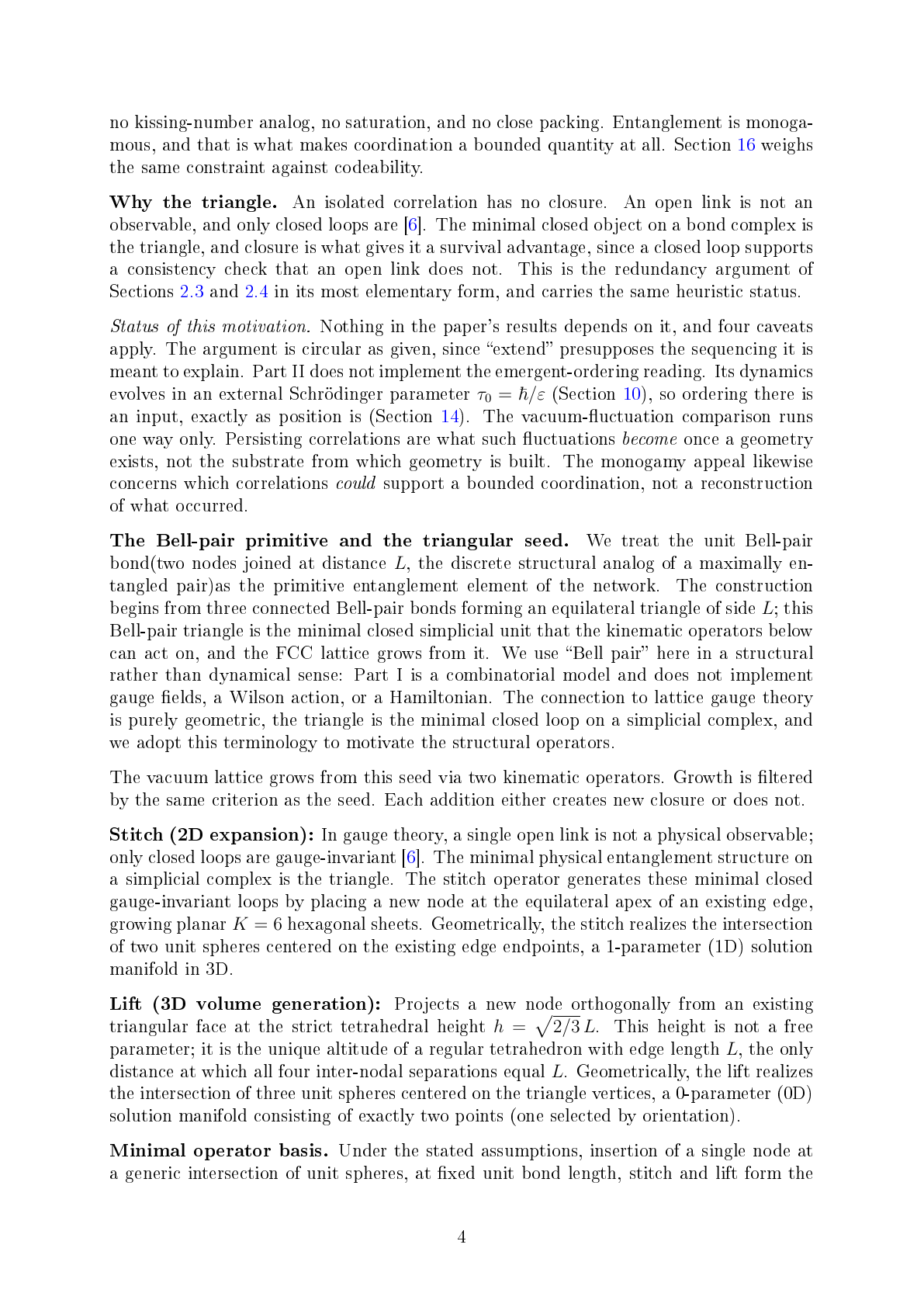
with Φ
T
(S) = S, where Φ
T
is a coarse-grained verification map. This is a consistency condition,
not a process. It needs no clock, no space and no measure, so it can be stated in a state that has
none of these. Selection rules of the familiar kinds need something that state lacks: a dynamical
selector needs time, a local one needs space, and a cost-based one needs energy. The principle
has known relatives. Quantum Darwinism selects the states whose records survive copying [11].
Constructor theory founds physics on which transformations are possible [12]. The persistence
postulate applies the same logic one level up, to the rulebook itself.
What persists: checked bonds of one length. In the SSM the principle takes a concrete
form. Proto-qubits entangle at random. Most of these entanglements do not last. A bond persists
only if it meets two conditions. It must have the common length L to within a tolerance δ, so
that it fits with the bonds already there. And it must be checked: it must lie on a closed loop
of bonds, so that an error on it is detected and can be corrected (Section 2.4). We propose that
random formation, filtered by these two conditions, is one uniform probabilistic mechanism that
both creates space and maintains it. The same rule applies everywhere and at every step. No
direction, place or time is preferred, and nothing is tuned.
2.3 Why quantum mechanics
The principle on its own does not select quantum theory. Classical systems also have fixed points,
stable attractors, conserved quantities, lasting correlations and error-correcting codes, so Φ
T
(S) =
S has classical solutions. A selection result needs further conditions on Φ
T
, on the state space and
on which correlations count. We first give three motivations, and then an exact result that closes
the gap to classical theory under two stated premises.
Relation without geometry. Before space exists, a relation between two degrees of freedom
cannot be carried by anything in between. Entanglement is a relation that needs no medium, no
distance and no history. Constructions of geometry from entanglement [1, 13, 14] then read as
the promotion of the only available relation into space. Classical correlations can be written down
abstractly, but realizing them physically needs a carrier or a structure already in place.
Variation with heredity. Building structure by selection needs variation, to try new config-
urations, and heredity, to keep the ones that work. A deterministic rulebook has heredity without
variation: the first triangle is never tried. Pure noise has variation without heredity: the triangle
dissolves. Quantum theory has both. Outcomes are random, but the law that governs them never
changes, and unitary evolution keeps what exists.
Self-checking without a substrate. Classical error correction exists, but it runs on physical
carriers. Before any carrier exists, a structure must check itself using only its relations. Quantum
stabilizer states can do this, and Section 2.4 shows the smallest one.
An exact step: what a closed world without geometry allows. Two premises make
the setting of Section 2.1 precise.
(P1) Closed world. Before the lattice there is nothing outside the system: no environment and
no observer whose ignorance could define a probability mixture. The state of the whole is
therefore pure.
(P2) Adjacency is correlation. Two parts are related, and so can become adjacent, only if their
joint state is correlated (nonzero mutual information).
Under these premises three standard facts become selection conditions.
Lemma 1 (classical theory has no relations in a pure whole). In classical probability theory the
states of a composite system are probability distributions on the product of the parts’ configura-
tions. Its pure states are point masses, and every point mass is a product of point masses on the
parts [15]. So every pure classical state has zero mutual information between any two parts. By
(P1) and (P2), a classical world before geometry has no relations at all: no adjacency, no graph
4
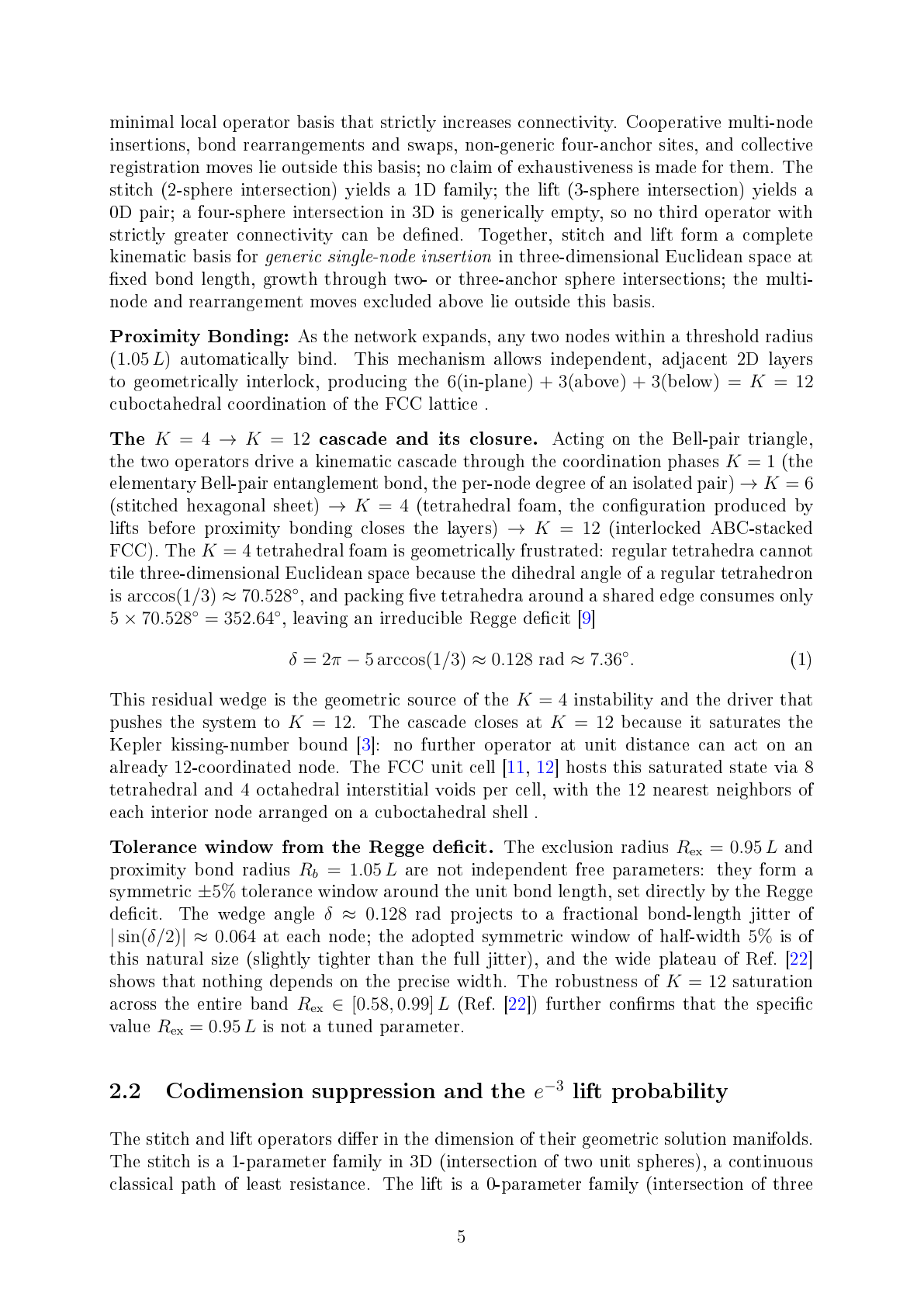
and nothing that could persist as structure. A theory passes this test only if it has pure states of
composite systems that are not products. Quantum theory has them: the entangled states.
Lemma 2 (monogamy makes adjacency sparse). If qubits A and B are in a pure maximally
entangled state such as |Φ
+
⟩, the joint state of A, B and any other system C is |Φ
+
⟩⟨Φ
+
|
AB
⊗ρ
C
:
A is uncorrelated with everything else [16, 17]. A Bell pair is therefore exclusive while it forms. A
qubit can belong to one pair only, and a node with K bonds needs K qubits, as in the SSM. (After
the node checks of Section 8.2, the entanglement of the pairs becomes shared around loops; each
bond stays perfectly correlated, so it still counts as adjacency under (P2).) This plays for bonds
the role that exclusion plays for identical fermions, though it is a different principle. Classical
correlation has no such limit: a perfectly correlated bit can be copied to any number of partners
(classical states can be broadcast; quantum states in general cannot [18]). Adjacency defined by
perfect classical correlation would join everything to everything, and so would not give a local
graph.
Lemma 3 (the triangle holds its information only in relations). The triangle state of Section 2.4
is pure, yet each of its three qubits, taken alone, is maximally mixed. All its information lies in
the relations between parts, and its checks read those relations. By Lemma 1, no pure classical
state has this property.
We checked all three statements numerically (Section 5). Together they give an exact con-
ditional: under (P1) and (P2), persistence of any structure requires non-product pure states, so
classical probability theory is excluded; if bonds must also be exclusive, correlations must be monoga-
mous, which classical correlations are not. This closes the classical gap that the motivations above
leave open, given the two premises. It does not select quantum theory among all non-classical
theories. Boxworld, the theory of Popescu–Rohrlich correlations stronger than quantum ones, also
has correlated pure states [15, 19]. It is excluded instead by its trivial reversible dynamics [20], in
which nothing can be grown.
These arguments connect to the reconstructions of quantum theory, which derive it from short
lists of informational axioms [21, 22, 23]. Table 1 reads the six principles of Ref. [22] as conditions
for persistence. Rival rulebooks are also known [24], and several fail in ways that read as failures
of persistence. Boxworld fails as described above. Quantum theory with real amplitudes fails
when independent parts are composed, and experiments have ruled it out [25, 26]. Higher-order
interference is also tightly bounded by experiment [27]. Classical probability theory satisfies five
of the six principles of Ref. [22] and fails only purification, the requirement that every mixed state
be part of a pure state of a larger system. Lemma 1 is the reason: a correlated pure state is what a
purification is. This points to the remaining step. If persistence, made precise, implies purification
in full, then together with the other five principles the theorem of Ref. [22] gives finite-dimensional
quantum theory. Lemmas 1–3 show that persistence under (P1) and (P2) already requires the
part of purification that classical theory lacks. Deriving the rest, and justifying the premises, is
the main open problem of this section.
2.4 How the first triangle forms, and why it lasts
Formation. Proto-qubits become entangled in pairs, at random. Define adjacency as a lasting,
checked relation: nodes i and j are adjacent if an entangled pair joins them, starting as a Bell
pair. A set of such pairs is a graph, and that graph is the first geometry. We propose that pairs
form and dissolve at random until three of them close a loop of equal bonds. That loop checks
itself, so it lasts while unchecked pairs do not. The first triangle is thus not designed or placed. It
is the first random configuration that passes the persistence principle.
Why a triangle: an exact statement. Use the reading of Section 8.3 with one qubit on
each bond and a Z check on each node (the product of Z over its bonds), and take as X-type
checks all operators that commute with the Z checks. (The FCC code of Section 8.3 keeps only
the octahedral loops among these, which is why it can have exposed bonds and logical qubits.) An
5
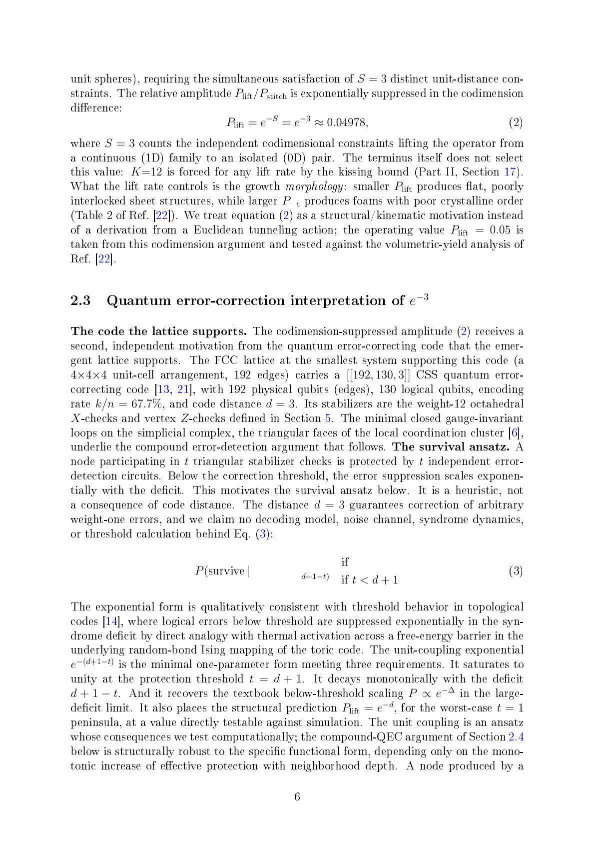
Table 1: The six informational principles of Ref. [22] read as conditions for persistence. The readings are
proposals (Table 2).
Principle Content Persistence reading
Causality No signaling from the future Completed links stay completed;
keeping structure needs a fixed past
Perfect
distinguishability
Non-mixed states can be told
apart perfectly
Errors can be detected: orthogonal
syndromes exist
Ideal compression Lossless encoding exists Structure can be encoded redundantly
and recovered
Local tomography Global states are fixed by local
data
Local checks certify global structure, as
in a stabilizer code on a lattice
Pure conditioning Measuring part of a pure state
leaves the rest pure
Reading a syndrome does not damage
what it checks
Purification Every mixed state has a pure
extension
Information is moved, never destroyed
X-type operator commutes with every Z check exactly when each node meets an even number of
its bonds, that is, when its bonds form closed loops. So the X-type checks available on a graph are
its loops. An X error on a bond is always detected, by the Z checks at its two ends. A Z error on
a bond is detected only if some loop passes through that bond. On a single bond, or on any tree,
there is no loop, and Z errors go undetected. Every single-bond error is detected exactly when
every bond lies on a loop, that is, when the graph has no bridge. The smallest graph without a
bridge is the triangle. We checked by enumeration that no connected simple graph (at most one
bond per pair of nodes) with fewer than three bonds has this property, and that among graphs
with three bonds only the triangle does.
The triangle’s checks are Z
1
Z
2
, Z
2
Z
3
and X
1
X
2
X
3
on its three bond qubits (the third node
check, Z
3
Z
1
, is the product of the first two). They fix a single state,
|ψ
△
⟩ =
1
√
2
|000⟩ + |111⟩
, (1)
the three-qubit GHZ state. Every single-qubit error on it is detected, since an X or Y error flips
the node checks at both ends of its bond and a Z or Y error flips the loop check. The triangle is
therefore the smallest network that checks every part of itself. Under the persistence principle it
is the first structure that can last. In this reading a single bond carries one qubit and has no loop
to check it; three bonds close the first loop. The Bell-pair reading gives the same state. Three Bell
pairs, with one parity check at each node, give this GHZ state, written with two virtual qubits per
bond (Section 8.2).
The triangle in the finished crystal. The triangle remains the unit of checking in the FCC
code. The eight faces of an octahedron are triangles in two alternating classes, and every bond of
the octahedron lies in exactly one face of each class. So each X check of the code, on the twelve
bonds of an octahedron, is the sum of four triangular loops. The finished lattice checks itself with
the same loop that started it.
2.5 From the triangle to the lattice
The first clock. Before the triangle there are no intervals. The triangle’s cycle of checks defines
the first one. A rule that changed from one application to the next could not keep any structure,
so the surviving rulebook must apply the same law each time. On this reading, the uniformity of
physical law is a condition for persistence. The Page–Wootters mechanism [28], since illustrated
in the laboratory [29], is a known way for time to emerge from entanglement with a clock inside a
state that is globally static. That the triangle plays this role is our proposal, not the theorem’s.
Growth as persistence. The growth rules of Section 3 are the persistence principle applied
6
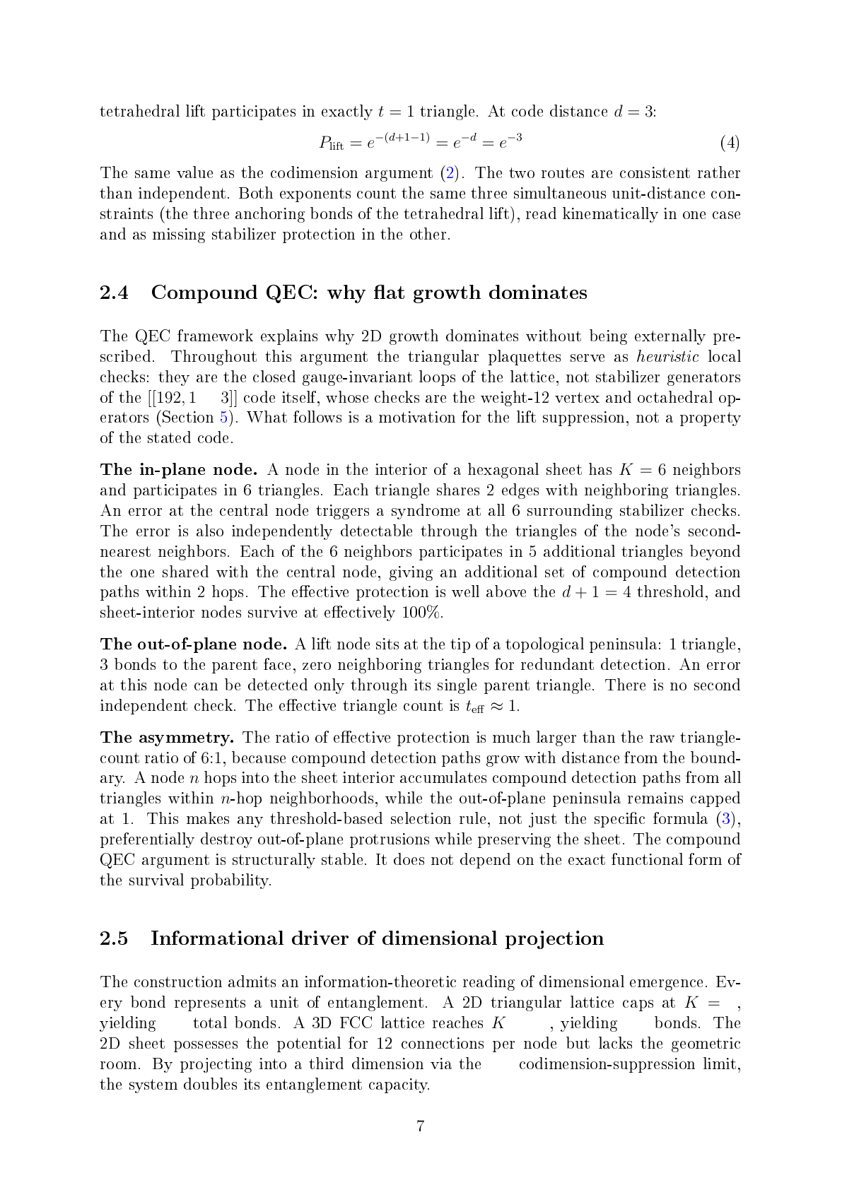
node by node. Candidate sites are tried at random, with weights set by the volume of positions
that meet the length condition (Section 4). A candidate is kept only if all its bonds have length L to
within δ. And every bond the rules create is checked from birth. Stitch bonds a new node to both
ends of an existing bond, closing a triangle. Lift bonds it to the three corners of a triangle, closing
three. Any further bond joins two nodes that are already connected, so it also closes a loop. The
grown network therefore never contains a bond that lies on no loop, which is why it has no bridge
(Section 8.3). Here a bond counts as checked if any loop passes through it, as in Section 2.4. The
FCC code of Section 8.3 uses only octahedral loops as checks, so in that code a bond on a triangle
can still be exposed. The lift rate itself, P
lift
/P
stitch
= (2
√
2/π)δ, is the relative probability that
a random attempt meets one more length condition. The simulations model creation in this way.
They model maintenance only through the unit-bond condition applied at placement (Section 3.4);
continued checking of the finished lattice is the role the SSM gives to the code of Section 8.3.
Growth from the seed. With the triangle in place, the rules of Section 3 take over. Stitch
builds new nodes from triangles alone, by x = a + b − c. The first lift completes a tetrahedron,
whose three edges at one corner are primitive vectors of the FCC lattice (Section 7.7). So the
seed triangle and the first lift fix the lattice and its orientation: every node that stitch adds from
triangles on that lattice lies on it. In the simulations this held for all but 17 of 485,073 such stitches,
while off-lattice lifts start twin grains (Section 7.7). The simulations then show what follows, and
they correct some expectations an origin story might have. Growth does not complete a flat sheet
before it goes up. After a few lifts it spreads in three dimensions, by stitching on the triangles
that join neighboring sheets (Section 7.6). It passes through no global K = 4 stage (Section 6).
And the stacking order needs no separate explanation, because stitch forces it (Section 7.7). This
proposal does not supply the remnant nodes whose trapping Section 7.5 studies. In the SSM they
come from an earlier disordered phase [2], which lies outside both this section and the simulations.
How that phase relates to the first triangle, whether it follows the seed or forms alongside the
growing lattice, is open.
Laws that arrive later. On this picture, the other laws switch on as the structures that
define them appear. Locality and a speed limit come with adjacency, since distance is a count of
bonds; the Lieb–Robinson bound [30] gives finite propagation speed in any local lattice system.
Energy comes with the first clock. Mass comes with the first trapped defect, as the cost of checking
it [3], so the triangle and the perfect lattice carry none. Thermal behavior comes with size: a small
part of a large entangled pure state is almost always thermal [31], and three qubits are too few for
that.
2.6 Status of this section
Table 2 separates what this section proves from what it proposes. The section derives no rate
for forming the first triangle and gives no dynamics for it. It makes no observational prediction
about the state before the lattice, which no instrument made of lattice can reach. Two results
would count against it: a derivation of quantum theory from a weaker principle, which would
make persistence redundant, and a reason to reject premise (P1) or (P2), which would reopen the
classical case.
7
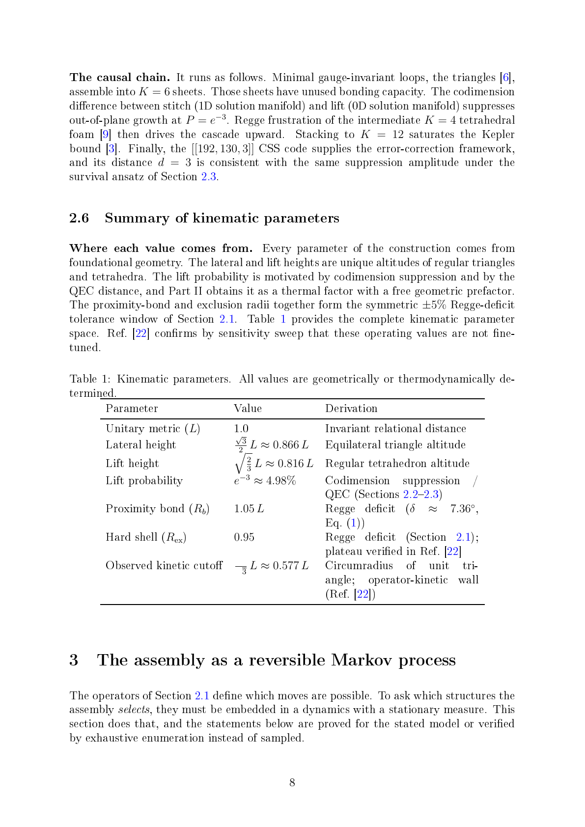
Table 2: Status of the claims in Section 2.
Claim Status
With one qubit per bond, the triangle is the smallest simple
network in which every bond lies on a loop, so node and
loop checks detect every single-bond error (Section 2.4)
Proved; checked by enumeration
The triangle’s checks fix the three-qubit GHZ state, which
detects every single-qubit error and whose single qubits are
maximally mixed
Proved
Bell pairs with one parity check per node equal the
edge-qubit code state (GHZ for the triangle), so the two
readings are related by node projections
Proved (Section 8.2); checked
numerically
This state is prepared deterministically: node parity
measurements plus
¯
X repair strings give it exactly for every
outcome
Proved (Section 8.2); checked for
every outcome on small graphs
Each octahedral X check of the FCC code is the sum of four
triangular loops
Proved
Every bond created by the growth rules lies on a loop when
it forms, so the grown network has no bond outside every
loop (Section 2.5); with octahedral checks only, some bonds
are still exposed (Section 8.3)
Proved from the rules; confirmed for
every node of two grown clusters
The lift rate is the relative probability that a uniform
random attempt meets one more length condition
Derived (Section 4); checked by
Monte Carlo
The seed triangle and the first lift fix the lattice for every
stitch from on-lattice triangles
Proved for ideal triangles; confirmed
for all but 17 of 485,073 stitches
(Section 7.7)
Growth is not sheet-first, has no global K = 4 stage, and its
stacking is forced
Simulation results (Sections 6, 7.6,
7.7)
Before the triangle there was no space, time, size or energy
ledger (Section 2.1)
Proposal; uses standard physics
(Noether, entanglement energetics)
This state is the SSM’s black-hole interior condition without
an exterior
Proposal
What exists is what can persist (Section 2.2) Foundational postulate, between the
weak (epistemic) and strong
(ontological) readings; not derived
Bonds arise from random entanglement and persist only if
they have length L within δ and are checked; this one
uniform mechanism creates and maintains space
Proposal; creation is simulated and
one round of repair is proved
(Section 8.2); repair under continuing
noise is not modeled
Under a closed world (P1) and adjacency as correlation
(P2), persistence excludes classical probability theory, since
classical pure states of composites are products (Section 2.3)
Proved, given (P1) and (P2)
Bell pairs are exclusive (monogamy), so adjacency by
maximal entanglement is sparse; classical correlation is not
Proved (standard results [16, 18])
Persistence selects quantum theory among all theories Open; would follow if persistence
implies purification in full, together
with the other five principles of
Ref. [22]
The informational axioms read as conditions for persistence
(Table 1)
Research program
Boxworld, real-amplitude quantum theory and higher-order
interference fail
Established results [20, 25, 26, 27]
The first structure to last is the one that checks itself fully Proposal
The triangle’s checks define the first clock Proposal; Page–Wootters is a known
mechanism [28]
Locality, energy, mass and thermal behavior arrive as their
structures appear
Proposal; the cited mechanisms are
theorems [30, 31]
8
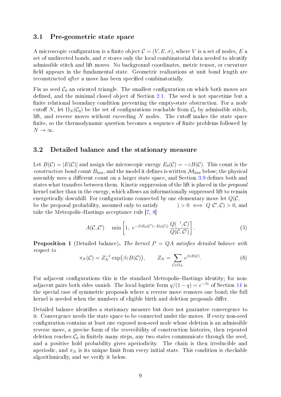
3 Model
The model rests on five rules: unit-length bonds, two growth operators, hard-shell exclusion,
proximity bonding and a unit-bond condition (Section 3.4). Lengths are in units of L = 1.
3.1 Bonds and initial conditions
Every bond is a Bell-pair bond of length L. A cluster starts from three nodes joined by three
bonds, which form an equilateral triangle of side L (Section 2.4). A slab starts from one complete
close-packed sheet, periodic in x and y (Section 3.6).
3.2 Growth operators
With lift in both directions, every triangle offers five growth sites. Stitch offers three, one per
edge. It places a node in the plane of the triangle, across that edge, on the side away from the
third corner, at distance (
√
3/2)L from the edge midpoint. Lift offers two. It places a node on the
normal through the centroid, at the tetrahedral height
h =
p
2/3 L ≈ 0.8165 L, (2)
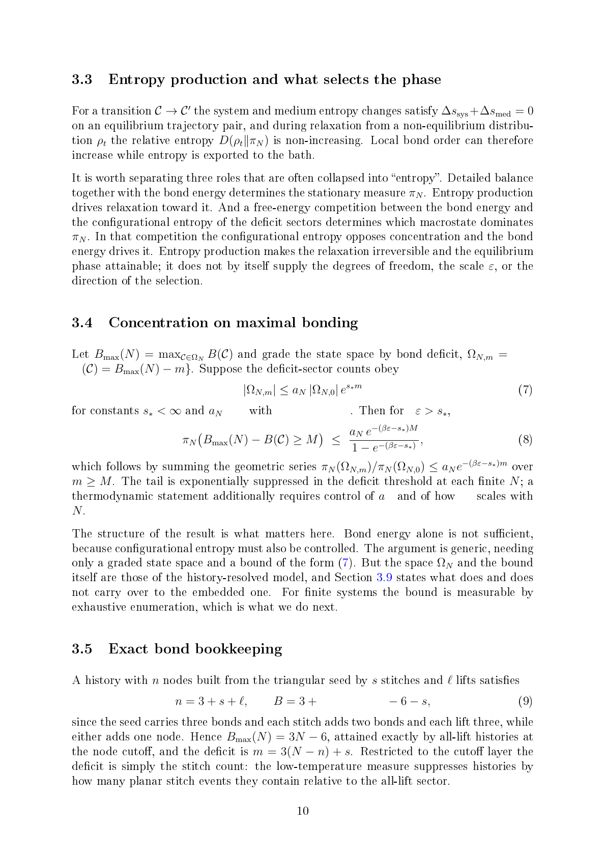
one above the triangle and one below (Fig. 1a). A candidate is rejected if any node lies closer
than the exclusion radius r
ex
(0.95L by default). An accepted node bonds to every node within
r
b
(1.05L by default). Together these defaults set the bond tolerance, δ = 0.05. New bonds make
new triangles, and these add new sites.
A triangle lies either within a sheet or between two neighboring sheets. A between-sheet triangle
has two corners in one sheet and one in the next. Such triangles are faces of the tetrahedra and
octahedra between sheets. They lie in the inclined close-packed planes of the crystal. Stitch and
lift act on both kinds, and every sheet stays flat. The step-edge view (Section 1) shows these
triangles in 3D.
3.3 Kinetics
Sites are drawn at random by weight. Each stitch site has weight 1, and each lift site has weight
w per direction. At each step, lift is chosen with probability wN
L
/(wN
L
+ N
S
), where N
L
and N
S
count the open lift and stitch sites, and stitch otherwise. A site of the chosen kind is then picked
uniformly. Section 4 derives w = (
√
2/π)δ ≈ 0.0225 for a bond tolerance δ = 0.05. Nodes never
move, and exclusion only grows. So a blocked site stays blocked, and a used site is filled. Each
site is tried once and then removed. For comparison with earlier work, we also use a legacy rule,
in which each step picks lift with a fixed probability p whenever a lift site is available. In both
schemes a node’s index equals its creation time. The first t nodes are thus the exact state of the
cluster at time t. A cluster stops at N nodes, and a slab stops after a set number of layers’ worth
of nodes.
3.4 Unit-bond condition
After placement, a node with three or more bonds is moved to make its bonds as close to L as
possible. It minimizes
E(x) =
X
j
|x − p
j
| − L
2
(3)
over its bonded partners p
j
, using four Gauss–Newton steps. The move is undone if it exceeds
0.02L or breaks exclusion or bonding. This is the direct reading of the rule that every bond has
length L. It is also needed for stability. Without it, position errors grow by about 30% per layer
9
stitch
top view
a
lift (+)
lift ( )
p
2
/
3
L
side view
0.000 0.025 0.050 0.075 0.100
bond tolerance
δ
0.00
0.02
0.04
0.06
0.08
0.10
P
lift
/P
stitch
(both directions)
e
−
3
(earlier value)
b
Regge-closure range of
(2
p
2
/π
)
δ
exclusive form
r/
(1
−
r
)
Monte Carlo
Figure 1: Growth operators and the lift rate. (a) Stitch places a node in the plane of a triangle across one
edge (top view); lift places a node at height
p
2/3 L above or below the centroid (side view, triangle edge-on).
(b) Ratio of lift to stitch acceptance volumes against bond tolerance δ, both lift directions: leading-order
result (2
√
2/π)δ (solid), exclusive form r/(1 −r) (dotted) and Monte Carlo integration (4 × 10
7
points per
value). The shaded band is the range of δ, about 2–5%, set by closing the Regge deficit (Section 4); the
dashed line is the earlier assignment e
−3
.
(Appendix A). All slab runs (Section 7), the lattice check of Section 7.7 and the quantum analysis
of Section 8 use it. The cluster sweeps of Section 6 do not, and Section 9 shows that this changes
them only slightly.
3.5 Lift orientation
We study three lift orientations. With both, every triangle offers a lift above and a lift below. With
axis, a triangle offers only the lift on the side whose normal points toward +z (both, if the triangle
is vertical). This is one global lift orientation. With radial, a triangle offers only the lift that faces
away from the seed.
3.6 Two growth geometries
A cluster models the start of growth. The crystal grows outward from a seed in every direction,
and sheets form both above and below the seed plane.
A slab models a patch far from the seed. There the growth front is so large that it is flat on
a local scale. It moves in one direction, with crystal behind it and empty space ahead. In the
SSM, the observable universe would be such a patch. The slab’s starting sheet, at z = 0, is the
crystal already grown. No node may be placed below it, and it offers lifts only upward. The slab is
periodic in x and y, with an n
x
×n
y
rectangular cell of a close-packed sheet (n
y
even). Its periodic
sides stand for a front much wider than the patch.
The growth viewer (Section 1) shows both geometries node by node. The simulations test
growth geometry in each case. They do not test whether our universe is such a patch.
10
4 The lift rate from tolerance volumes
Lift is rare because it must meet one more distance condition than stitch. Each extra condition
costs one factor of the bond tolerance δ. Earlier work fixed a per-step lift probability P
lift
= e
−3
[2].
Here we derive the rate.
4.1 Acceptance volumes
A bond is accepted if its length lies within L(1 ± δ). So a new node has a small volume of
acceptable positions. We take each operator’s weight to be proportional to that volume. This
assumes that every position near the front is equally likely to be tried, and the derivation rests on
that assumption. It is the uniform random formation of Section 2.2: positions are tried at random,
and only those whose bonds are within tolerance persist.
The scaling follows from the shapes. Points at distance L from one node form a thin shell.
Two shells, as in stitch, meet in a thin ring. The ring is long and thin only in cross-section, so
its volume scales as δ
2
. Three shells, as in lift, meet in two small blobs. These are thin in every
direction, so their volume scales as δ
3
. The ratio is therefore linear in δ. The calculation below
gives the prefactor.
A stitch needs unit distance to both ends of an edge. Two shells of radius L and thickness 2δL,
with centers L apart, meet in a thin torus. The torus runs around a circle of radius (
√
3/2)L. The
shell normals meet at 60
◦
there, so the cross-section is a parallelogram of area (2δL)
2
/ sin 60
◦
. To
leading order,
V
stitch
= 2π ·
√
3
2
L ·
(2δL)
2
sin 60
◦
= 8π δ
2
L
3
. (4)
A lift needs unit distance to all three corners of a triangle. Three shells meet in two small paral-
lelepipeds, one above and one below. Each has volume (2δL)
3
divided by the determinant of the
three unit normals. For a regular tetrahedron that determinant is 1/
√
2. Counting both directions,
V
lift
= 2 × 8
√
2 δ
3
L
3
= 16
√
2 δ
3
L
3
,
P
lift
P
stitch
=
V
lift
V
stitch
=
2
√
2
π
δ ≈ 0.90 δ. (5)
Per direction the ratio is (
√
2/π)δ ≈ 0.45δ. The factor of two comes from the two directions. At
δ = 0.05 the ratio is 4.50% for both directions and 2.25% per direction. In the simulation this gives
weight 1 per stitch site and w = (
√
2/π)δ per lift site. The stitch weight counts the whole ring,
although stitch then places the node at the in-plane point on it. Each lift apex is at distance L
from both ends of every edge, so the lift regions lie inside the stitch tori. If stitch means placement
with exactly two bonds, the ratio becomes r/(1 − r), with r = (2
√
2/π)δ. This changes 4.50% to
4.71% at δ = 0.05, a change of order δ
2
. The simulations use the first form.
4.2 Monte Carlo check
We sampled 4 × 10
7
random points around a unit triangle. We counted those within tolerance of
two corners (stitch) and of all three (lift); see Table 3 and Fig. 1b. All values agree with theory
within the sampling noise. That noise is about 2% for the lift counts at δ = 0.05 and larger at
δ = 0.02, where lift volumes are about 16 times smaller. The δ = 0.02 row comes from a separate
run.
4.3 What sets δ
The derivation does not fix δ. One natural scale is the strain needed to close the Regge deficit [32].
Five regular tetrahedra around a shared edge leave a gap of 2π − 5 arccos(1/3) ≈ 0.128 rad.
Stretching the shared edge closes it at 5.2% strain. Stretching the five rim edges closes it at 1.8%,
11
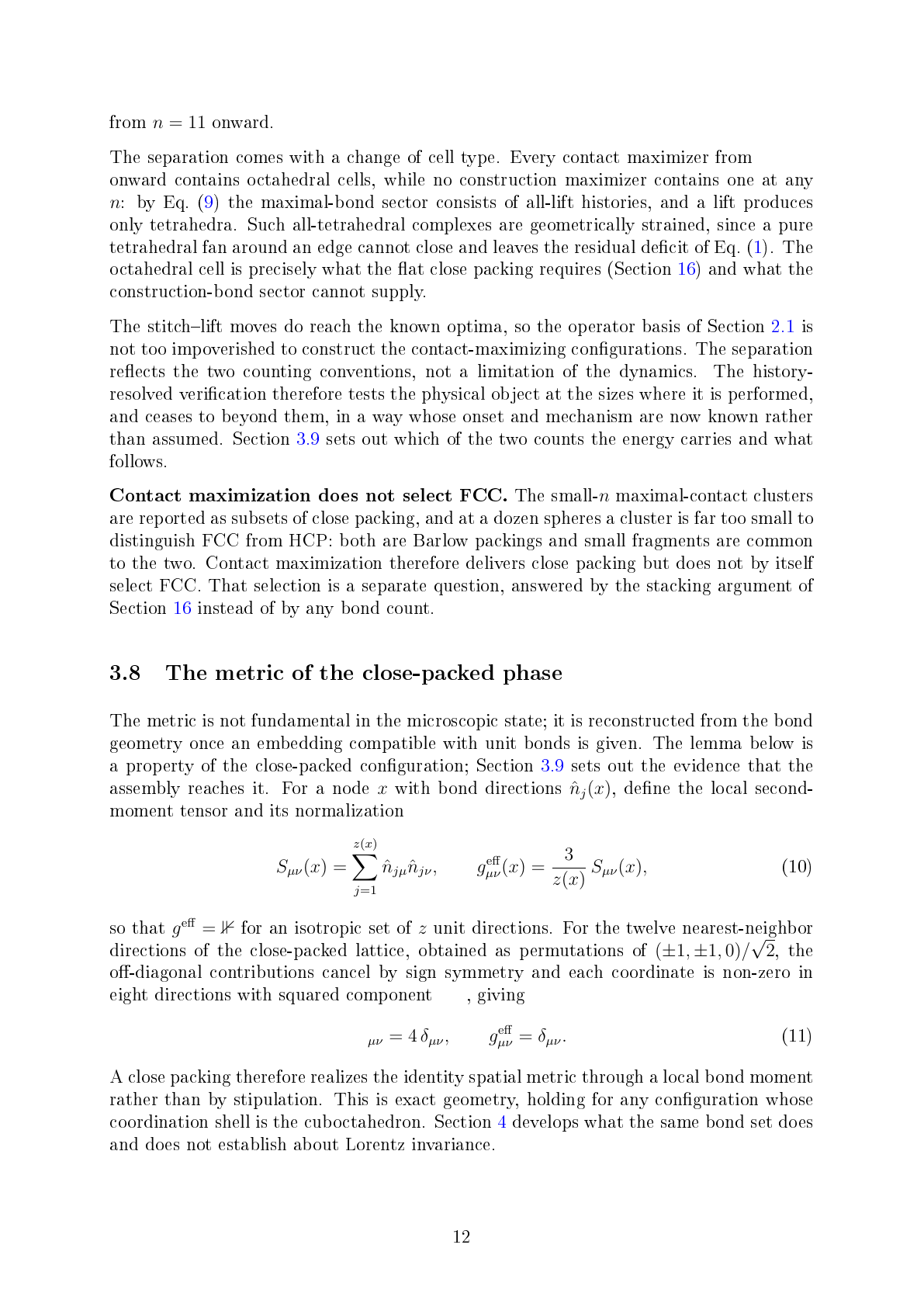
Table 3: Monte Carlo check of the acceptance volumes (δ = 0.05 unless stated).
Quantity Monte Carlo Theory
Stitch volume, one edge (L
3
) 0.06287 0.06283
Lift volume, above (L
3
) 0.001399 0.001414
Lift volume, below (L
3
) 0.001442 0.001414
Lift volume, both (L
3
) 0.002841 0.002828
Ratio, both directions 0.0452 0.0450
Ratio at δ = 0.02 0.0175 0.0180
with less elastic energy. This is a heuristic, not a derivation. The geometry places δ between about
1.8% and 5.2%. The lift-to-stitch ratio then lies between about 1.6% and 4.7%.
The weight w is not the share of placements that are lifts. Most lift sites are blocked when
drawn. At w = 0.0225 per direction, only 0.66% of placements are lifts. The legacy setting p = 0.05
gives about 1%. We report the realized lift fraction throughout.
5 Methods
Implementation. The simulator is written in Python and compiled with Numba [33]. Neighbor
search uses a uniform cell grid, periodic in x and y for the slab. Site lists use swap-removal, so each
attempt costs O(1) apart from the local search. A cluster of 10
6
nodes grows in about 20 s on one
core. Runs are deterministic for a given seed, and each node records the triangle it was built on. A
test suite checks the structure classifier on perfect FCC, hcp and icosahedral environments. It also
checks that bond lengths lie in [r
ex
, r
b
), that exclusion holds and that runs reproduce exactly. Six
further tests reproduce the published parameters of the FCC code [7] (Section 8.3), check the Bell-
pair to edge-qubit construction, its entropy formula and its deterministic preparation (Section 8.2),
check the exact triangle results of Section 2.4, check that every new node closes a triangle when it
forms (Section 2.5), and check Lemmas 1–3 of Section 2.3.
Structure classification. We classify each node by common neighbor analysis (CNA) [34, 35],
with cutoff (1 +
√
2)L/2 ≈ 1.207L. A node with 12 neighbors is FCC if all bonds have signature
(4,2,1). It is hcp if six have (4,2,1) and six have (4,2,2), and icosahedral if all have (5,5,5). Any
other node is labeled other. CNA uses geometric neighbors within the cutoff, while tetrahedra are
counted on the bond graph. Positions lie within about 10
−8
L of ideal sites (Section 9), so a fixed
cutoff is safe; results do not change for cutoffs from 1.15L to 1.25L. We also count the bonded
tetrahedra (4-cliques) that contain each node. A node in perfect FCC is in 8, an icosahedral node
in 20, and a neighbor of a single vacancy in 6.
Bulk and depth. A node is bulk if at least 42 nodes lie within 2L, the population of the
first three FCC shells [2]. This test still admits the first layers below a rough surface, so we also
compute depth. Non-bulk nodes have depth 0. A node at depth d lies within 1.2L of a node at
depth d − 1, with d the smallest such value.
Slab analysis. The stacking axis z is the substrate’s [111] direction. A node is on-lattice if
its height is within 0.05h of a layer height kh. Its lateral registry is the nearest of the close-packed
positions A, B and C, with the substrate as A. In a layer with k not divisible by 3, an ABC
domain has registry k mod 3, and its mirror twin ACB has (−k) mod 3. The twin imbalance is
|f
ABC
− f
ACB
|/(f
ABC
+ f
ACB
), in bins of 10 layers. Twin fractions count only on-lattice nodes.
A bonded tetrahedron is up if three corners share a layer and the fourth is one layer above. It is
down if the fourth is one layer below. A perfect FCC or hcp crystal has equal numbers of each.
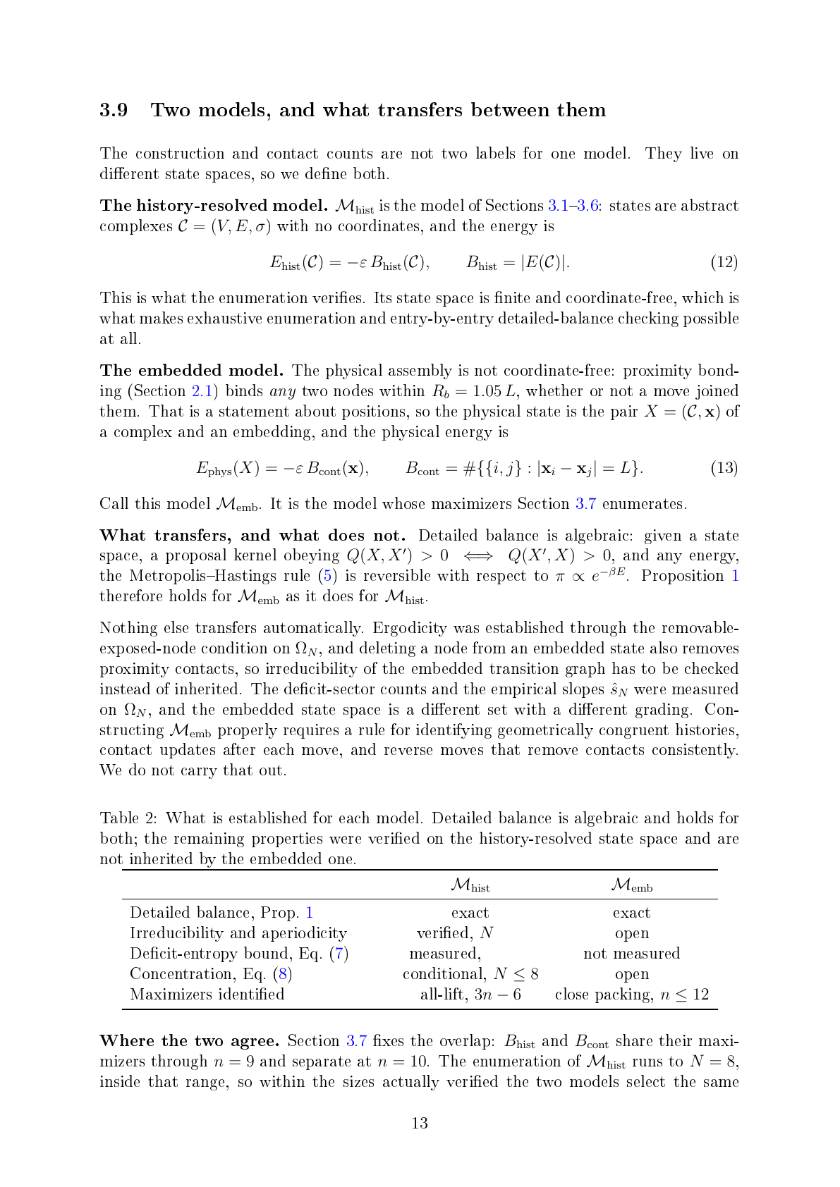
Runs. Table 4 lists the runs. With 8 remnant-trapping slabs (Section 7.5), 2 sheet-formation
slabs (Section 7.6) and 6 lattice-check clusters (Section 7.7), 24 robustness runs (Section 9) and 32
runs for the quantum analysis (Section 8), the study has 696 production runs. Smaller diagnostic
12
runs are not counted: the six depth-bias slabs and the four layer-pair slabs of Section 7.4 and
the comparison runs of Appendix B. Uncertainties, where shown, are standard errors over seeds.
Methods specific to Sections 7.5–7.7 and to Section 8 are given there.
Table 4: Simulation sets of Sections 6 and 7.1–7.3.
Set Geometry Size Varied Seeds/point Runs
Size scaling cluster, both N = 10
3
–10
6
N (7) 32–4 156
Lift sweep cluster, both N = 10
5
w = 5 × 10
−4
–1 (11) 8 88
Legacy rule cluster, both N = 10
5
p = 0.01–0.4 (6) 8 48
Exclusion sweep cluster, both N = 3 × 10
4
r
ex
= 0.50–1.02L (27) 4 108
Orientation, size cluster, axis/radial N = 10
3
–10
6
N (4) 16–4 88
Orientation, lift cluster, axis N = 10
5
w (11) 8 88
Slab periodic slab, axis/both 32
2
, 48
2
, 64
2
width, orientation 8 48
Total 624
6 Results I: growth from a seed
This section covers clusters grown from the three-node seed. Its runs use the bare rule, without
the unit-bond condition (Section 3.4); Section 9 gives the small effect of adding it.
6.1 The interior is FCC
At N = 10
6
, nodes at depth 4 or more are 98.5–98.7% FCC in every depth shell from 4 to 11. Their
hcp fraction is below 10
−4
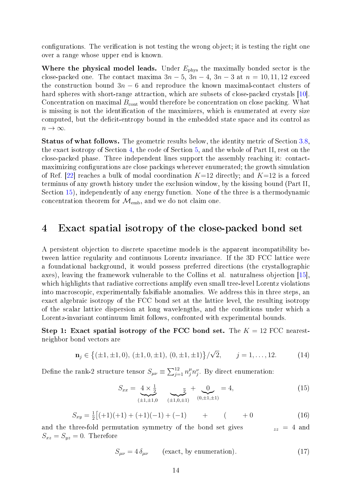
, and no icosahedral node appears at any size (Fig. 2a,b). Among bulk
nodes, 94% belong to exactly 8 bonded tetrahedra and 3.4% to 6. Six is the count for a vacancy
neighbor. Each vacancy has twelve neighbors, so this is consistent with about 0.3% vacant sites.
The interior defects therefore look like isolated vacancies rather than stacking faults, and they
show as isolated pockets in Fig. 2a. A vacancy can form in a growth that only adds nodes: a site
is enclosed after every triangle that could have filled it has been used.
6.2 Finite-size scaling
The FCC fraction rises with size (Table 5). The bulk fraction levels off near 94%, because the 42-
neighbor test counts the first three layers below the surface. Those layers (depths 1–3) are 69–96%
FCC. The depth-resolved value of 98.5–98.7% is the better measure of the interior. The non-FCC
fraction over all nodes falls with an effective exponent of 0.23 over N = 10
3
–10
6
(Fig. 2c). A
monolayer surface would give N
−1/3
. The disordered region is thus a few layers thick, as expected
for a rough growth front. Ref. [2] used N
−1/3
.
Table 5: Finite-size scaling. Isotropy is the ratio of smallest to largest eigenvalue of the position covariance.
N Seeds Bulk FCC Bulk hcp All-node FCC Lift fraction Isotropy
10
3
32 0.859 ± 0.011 0.0032 0.419 ± 0.007 0.0082 0.62
3 × 10
3
32 0.892 ± 0.009 0.0024 0.552 ± 0.007 0.0070 0.71
10
4
32 0.914 ± 0.007 0.0021 0.664 ± 0.006 0.0068 0.80
3 × 10
4
32 0.927 ± 0.005 0.0018 0.743 ± 0.005 0.0066 0.86
10
5
16 0.941 ± 0.003 0.0009 0.813 ± 0.004 0.0066 0.91
3 × 10
5
8 0.942 ± 0.004 0.0009 0.849 ± 0.006 0.0066 0.93
10
6
4 0.943 ± 0.005 0.0008 0.877 ± 0.007 0.0066 0.95
13
25 0 25
y
(
L
)
40
20
0
20
40
z
(
L
)
a
fcc other hcp
0 5 10
depth below surface (hops)
0.0
0.2
0.4
0.6
0.8
1.0
fraction
b
fcc
hcp × 100
10
3
10
4
10
5
10
6
N
0.4
0.5
0.6
0.7
0.8
0.9
FCC fraction
c
fit
N
−
0
.
23
bulk
all nodes
Figure 2: Growth from a seed. (a) Central cross-section (|x − ¯x| < 0.45L) of a 3 ×10
5
-node cluster colored
by common neighbor analysis: the interior is FCC, with isolated vacancy pockets and a disordered surface
a few layers thick; hcp is essentially absent. (b) FCC and hcp (×100) fractions against depth below the
surface, N = 10
6
(4 runs). (c) FCC fraction against N for bulk and all nodes, with the fit 1 − f ∝ N
−0.23
.
6.3 Insensitivity to the lift rate
FCC does not need a tuned lift rate. The bulk FCC fraction is flat at 96–98% for realized lift
fractions below about 0.2%, and it falls steadily above that (Table 6). The legacy rule gives the
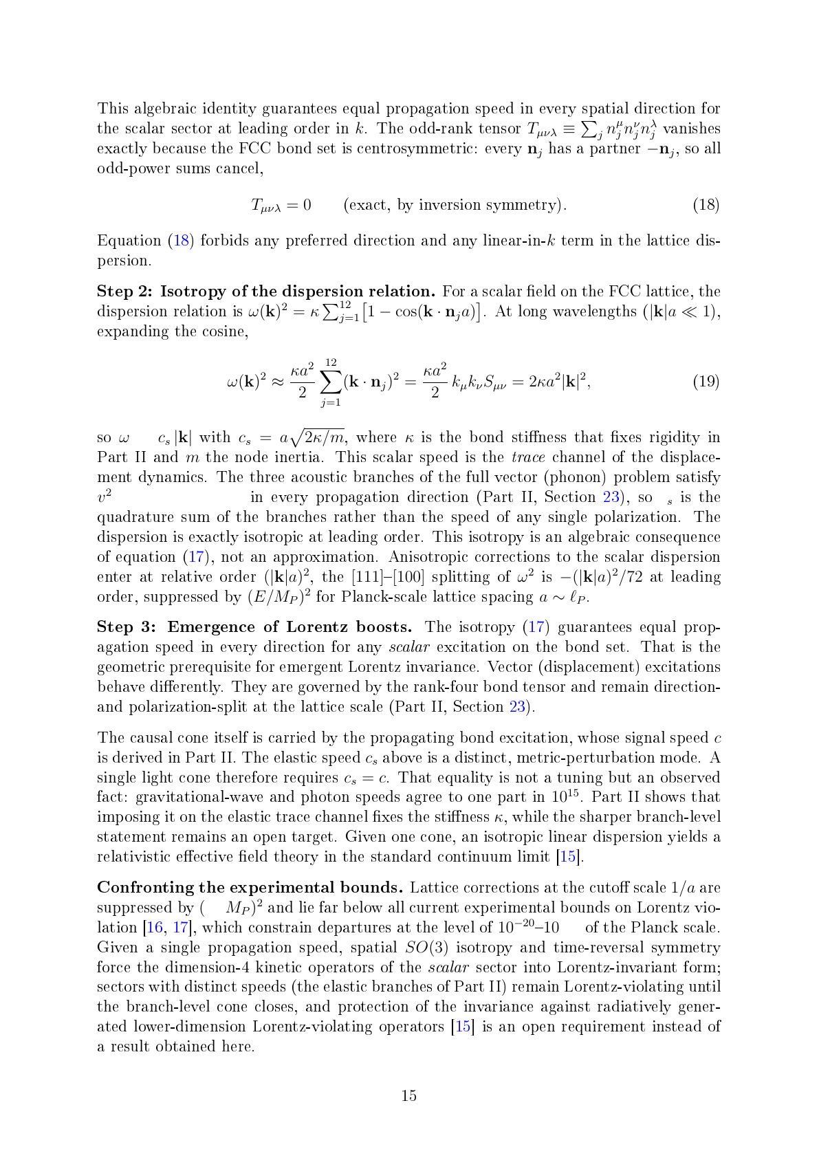
same curve against the realized lift fraction (Fig. 3a). Rare lift does not leave disconnected sheets,
contrary to the expectation in [2]. One lift per 10
4
placements still gives 97.5% FCC.
The reason is that stitch acts on every triangle, including the between-sheet triangles that a
lift creates. After a few lifts, growth spreads in three dimensions by stitching on these triangles
(Section 7.6). Lift then has two remaining roles. It rounds the cluster: the isotropy is 0.73 at the
smallest weight and 0.91 at the geometric one. It also creates stacking faults, and the hcp signal
grows with the lift rate.
Table 6: Lift sweep at N = 10
5
, 8 seeds per point.
w (per direction) Realized lift fraction Bulk FCC Bulk hcp Isotropy
0.0005 0.0001 0.975 ± 0.006 0.0001 0.73
0.001 0.0003 0.964 ± 0.007 0.0004 0.79
0.002 0.0006 0.962 ± 0.007 0.0004 0.81
0.005 0.0015 0.971 ± 0.005 0.0002 0.83
0.0113 0.0033 0.940 ± 0.006 0.0017 0.86
0.0225 (δ = 0.05) 0.0066 0.939 ± 0.004 0.0009 0.91
0.045 0.0132 0.893 ± 0.004 0.0020 0.90
0.1 0.0282 0.811 ± 0.006 0.0048 0.89
0.2 0.0554 0.691 ± 0.005 0.0107 0.86
0.5 0.129 0.505 ± 0.004 0.0286 0.82
1.0 0.225 0.370 ± 0.003 0.0576 0.82
6.4 Exclusion radius
Results are nearly identical for every r
ex
from 0.58L to 0.98L. Bulk FCC is 0.925–0.929 and
mean coordination is 11.14–11.16 at N = 3 × 10
4
. At r
ex
= 0.54L and 0.56L, no FCC forms and
mean coordination exceeds 12. At 1.00L the FCC fraction falls to 0.77, and at 1.02L no growth
14
10
4
10
3
10
2
10
1
realized lift fraction of placements
0.0
0.2
0.4
0.6
0.8
1.0
bulk fraction
geometric range
a
hcp × 10 (site rule, both)
site rule, both
site rule, one orientation
legacy per-step rule
10
2
10
3
10
4
10
5
10
6
growth time t (nodes placed)
0.0
0.2
0.4
0.6
0.8
1.0
b
bulk fcc fraction
tetrahedra per node / 8 (FCC = 1)
mean K / 12
fraction of nodes with K = 4
Figure 3: (a) Bulk FCC fraction against the realized lift fraction at N = 10
5
for the site-weighted rule
with lift in both directions, with one global orientation, and for the legacy per-step rule; dashed: hcp (×10).
The shaded band is the realized lift fraction for the geometric weight with δ between 2% and 5%. FCC is
best when lift is rarest. (b) Growth history of the N = 10
6
runs: bulk FCC, tetrahedra per node relative
to FCC, mean coordination relative to 12, and the fraction of nodes with K = 4, all against the number of
nodes placed. No tetrahedra-rich stage occurs.
is possible. The lower edge lies between 0.56L and 0.58L. This matches L/
√
3 ≈ 0.577L, the
distance from a triangle’s centroid to its corners. The plateau is flat because candidates almost
never fall at a distance in this range from an existing node. It is a check of the rules, not an
emergent transition. Runs at 0.50L and 0.52L overflowed the triangle buffer and are left out.
6.5 Growth history: tetrahedral units, but no K = 4 stage
Node index equals creation time, so every earlier state of a run is available exactly. In the four
N = 10
6
runs, all structural measures rise steadily toward their FCC values (Table 7, Fig. 3b).
The tetrahedron count never exceeds the FCC value of 8 per node, and no icosahedral node forms
at any time. Growth thus goes from the sheet-like seed straight to FCC, with no tetrahedra-rich
stage.
Locally, every lift makes a tetrahedral unit. The lifted node bonds to the three corners of its
triangle. The four nodes are then all bonded to each other and form the complete graph K
4
. These
units carry growth into three dimensions. In this local sense the tetrahedron is the natural step
between a sheet and the bulk.
This local unit differs from coordination K = 4, which is what K means in this paper. The
new corner of a tetrahedron usually has coordination 3. In one run of N = 10
5
(seed 0, with the
unit-bond condition), 173 of 665 lifted nodes (26%) had 3 bonds when placed, and 58 (9%) had 4.
The rest landed in partly built pockets with 5 to 12 bonds.
Nor is coordination 4 a stage that nodes stay in. Bonds are added one at a time, so a node
placed with fewer than 4 bonds must pass through 4 on its way to 12. Only 33% of nodes do so,
since most start with 5 or more bonds. Those that reach K = 4 leave it as fast as any other value
(Table 8). Nodes stay longest at K = 10 and 11, just before they fill up.
15
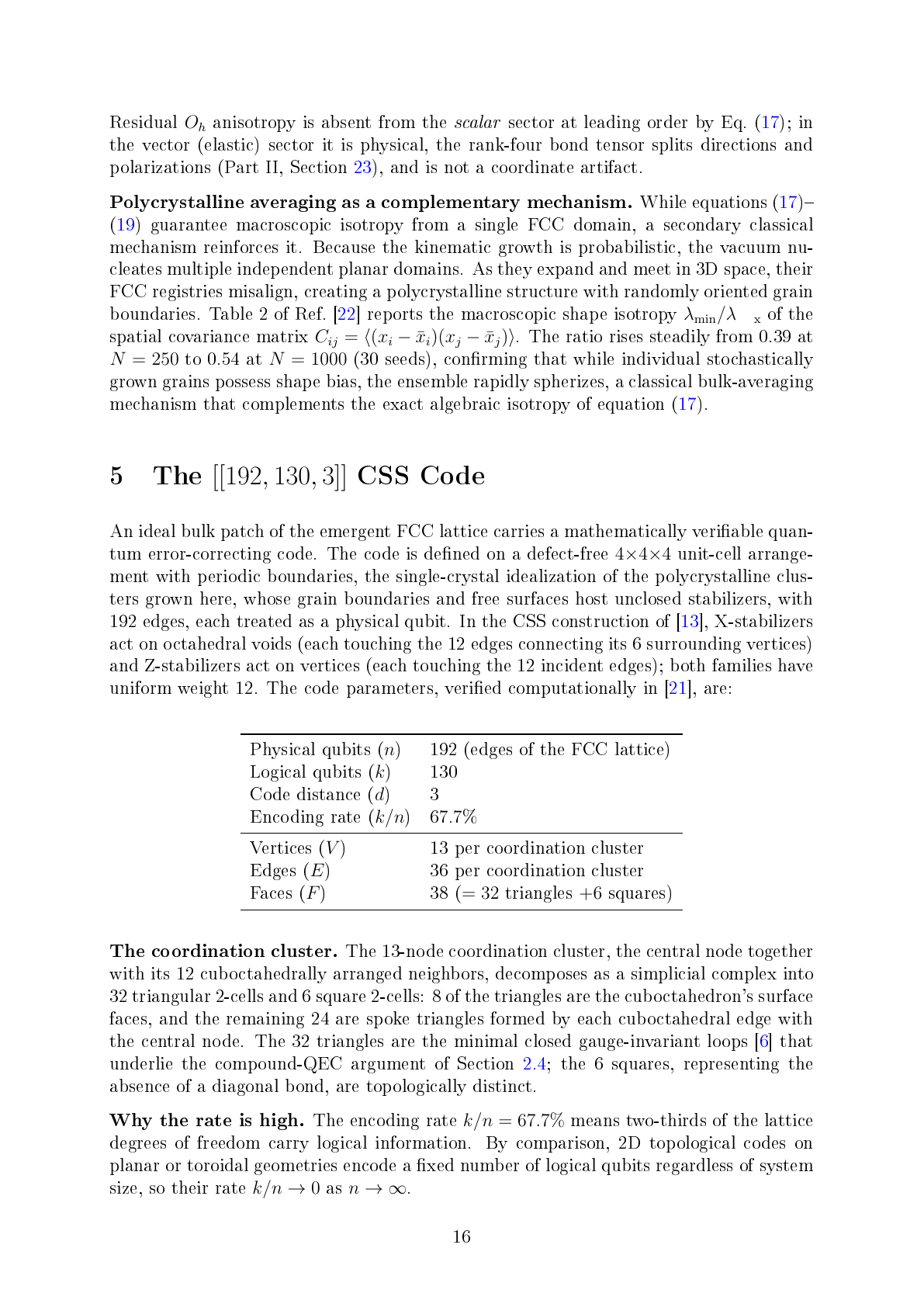
Table 7: Growth history of the N = 10
6
runs (4 seeds).
t (nodes placed) Bulk FCC Mean K Tetrahedra per node Fraction with K = 4
30 – 4.80 0.63 0.158
100 0.685 7.32 3.00 0.103
300 0.793 8.63 4.23 0.055
10
3
0.861 9.73 5.38 0.029
10
4
0.913 10.82 6.58 0.014
10
5
0.937 11.39 7.24 0.006
10
6
0.943 11.66 7.56 0.003
Table 8: Median number of placements a node spends at each coordination (nodes in the first half of an
N = 10
5
run).
K 2 3 4 5 6 7 8 9 10 11
Placements at K 526 453 430 410 423 455 496 579 722 1095
6.6 Lift orientation
The three lift orientations grow the same crystal (Table 9). The axis variant is slightly cleaner,
and almost all of the difference comes from its halved lift rate. At equal realized lift fractions the
two give the same structure. Lift in both directions gives 0.939 bulk FCC at 0.66%, and axis gives
0.939 at 0.65% (Fig. 3a). One-sided lift leaves no mark on the cluster’s shape. Under axis lift,
49.8% of nodes lie below the seed plane, and the cluster spans z = −56L to +56L at N = 10
6
.
Stitching on between-sheet triangles extends growth downward as fast as upward.
Table 9: Lift orientation at N = 10
6
. Interior FCC is the mean over depth shells 4 to 8.
Orientation Interior FCC (depth ≥ 4) All-node FCC Lift fraction Nodes with 6 tetrahedra
Both 0.985 0.877 0.0066 0.034
Axis (+z only) 0.992 0.896 0.0033 0.023
Radial (outward) 0.985 0.885 0.0061 0.032
7 Results II: a patch of the universe
A patch grows as twinned FCC. The two mirror-image stacking variants start evenly mixed. They
coarsen with height until one dominates, and the winner is random. All slab runs use the unit-bond
condition and w = 0.0225 per direction.
7.1 Overview
Table 10 summarizes the 48 production slabs. Their interior FCC fraction, 0.84–0.92, is below the
cluster value, because twin boundaries leave layers near the base about 91% full and tilted grains
lower it further in some runs.
7.2 Twin domains and their coarsening
The first layer above the substrate places nodes at B and C positions in about equal numbers.
These seed the two twin variants, ABC and ACB. Near the base, domain boundaries leave layers
about 91% full; higher up, as domains coarsen, layers fill to 97–99%. Every third layer is the
exception: it is A in both variants and fills completely. Higher up, one variant slowly takes over
16
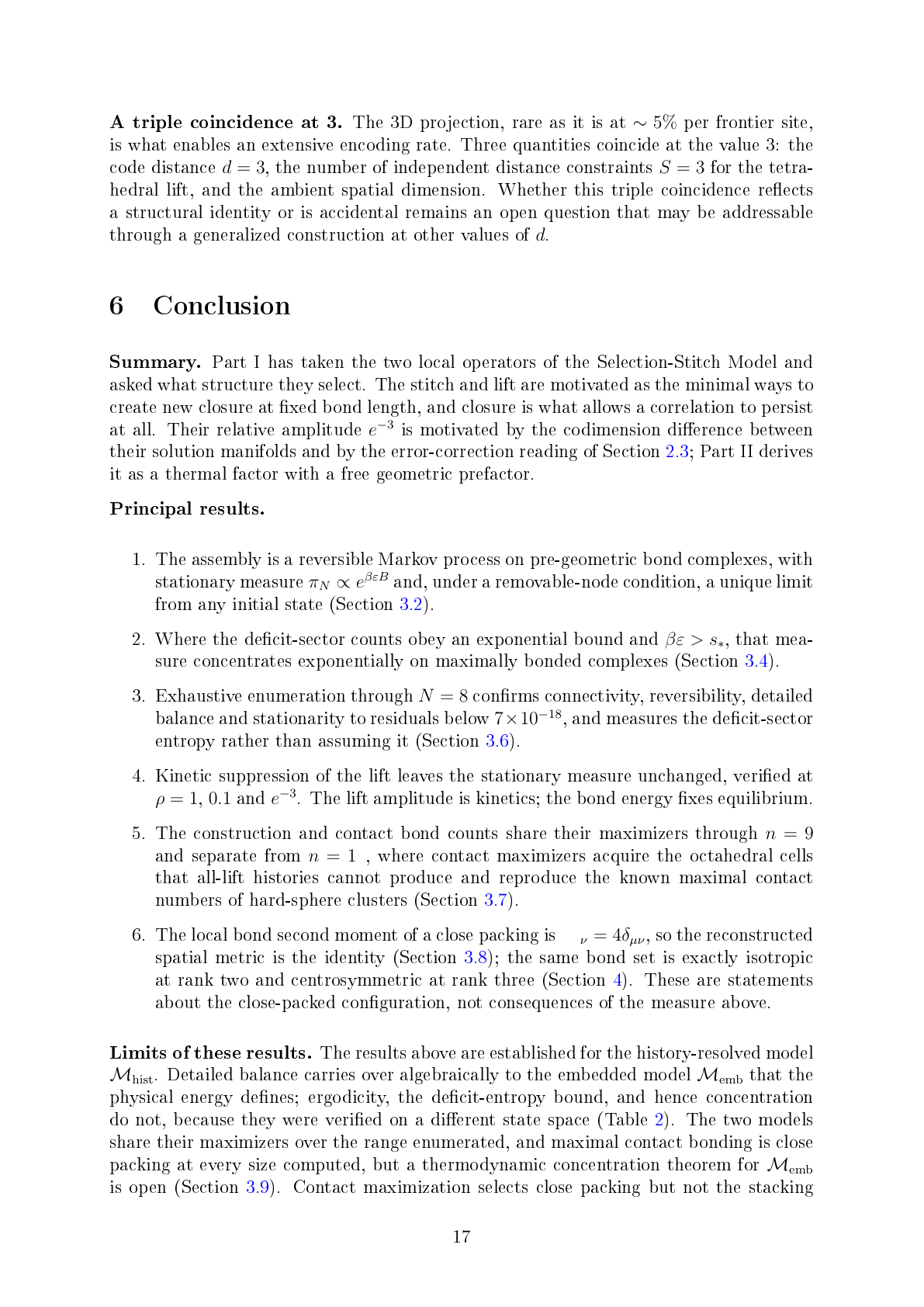
Table 10: Slab runs, 8 seeds per row. A tilted grain appears when the on-lattice fraction in any 10-layer
bin drops below 0.98, and takes over when it averages below 0.5 in the top three bins. Interior FCC counts
layers 2 to two below the top complete layer. For the last column see Section 7.4.
Width Layers Orient. Grain appears Takes over Final imbalance ABC wins Int. FCC (down−up)/total
32
2
600 axis 2 0 1.00 4 0.922 6.5 × 10
−4
32
2
600 both 5 2 0.81 2 0.873 10.1 × 10
−4
48
2
400 axis 2 2 0.75 4 0.868 9.2 × 10
−4
48
2
400 both 3 0 0.85 7 0.884 7.9 × 10
−4
64
2
300 axis 2 1 0.37 6 0.843 9.5 × 10
−4
64
2
300 both 1 1 0.74 4 0.853 11.5 × 10
−4
(Table 11; Fig. 4a,c). A 32-wide slab becomes a single variant by about layer 300. Wider slabs
take longer. An imbalance of 0.5 is reached near layers 65, 115 and 210 for widths 32, 48 and 64.
A power-law fit to these three points gives a height that grows roughly as width
1.7
, so domains
widen roughly as height
0.6
. An unbounded patch would never become a single variant at finite
height. Instead it forms single-variant domains that keep growing.
The winning variant is random. In the six takeover runs (Section 7.3), the winner is the
variant that dominates the remaining on-lattice nodes at the top. ABC won 27 of 48 runs (56%),
as expected for a fair coin, and lift orientation makes no difference. This follows from symmetry. A
vertical mirror plane swaps ABC and ACB but leaves +z unchanged. So no global lift orientation
can favor either variant.
Table 11: Mean twin imbalance against height, 16 runs per width.
Height (layers) 10 50 80 120 200 300
Width 32 0.23 0.45 0.55 0.77 0.94 1.00
Width 48 0.16 0.30 0.40 0.51 0.62 0.80
Width 64 0.11 0.18 0.23 0.32 0.48 –
7.3 Tilted grains
In 15 of 48 slabs, a grain grew whose close-packed planes are inclined to the substrate. In the case
we examined, it started when a lift on a between-sheet triangle placed a node off the substrate’s
layer heights. The grain then competes with the main crystal. It died out in 9 runs and took over
in 6, which became polycrystalline (Fig. 4b). At this sample size there is no clear effect of lift
orientation. Axis lift gave 6 events and 3 takeovers, and both gave 9 events and 3 takeovers. In
thin-film growth, grains whose fastest growth direction points along the growth direction tend to
win [36]. This is a likely mechanism here too. The nucleation rate and the takeover criterion need
more runs.
7.4 Tetrahedron orientation
In the SSM the two orientations of tetrahedral voids correspond to matter and antimatter [2]. A
front that moves one way makes the two classes distinct, so the void population could carry an
along-growth bias. We measured it directly in the slab, where depth below the front is clear. The
bias is confined to the outermost layers (Table 12, Fig. 5b). Below the top two layers there is no
meaningful along-growth bias.
A small residual signal remains. Counted layer pair by layer pair, down tetrahedra exceed up by
about 10
−3
where twin boundaries are present, with a three-layer pattern that tracks the domains.
In single-variant regions (layers 300–400 of 32-wide slabs), an excess of 4.2–5.3 × 10
−4
remains in
17
0 50 100 150 200 250 300
height (layers)
0
20
40
y
(
L
)
a
twin coarsening (64 × 64, lift both, seed 3)
ABC ACB other registry off-lattice (tilted) substrate
0 50 100 150 200 250 300
height (layers)
0
20
40
y
(
L
)
b
tilted-grain takeover (64 × 64, axis lift, seed 0)
0 200 400 600
height (layers)
0.0
0.2
0.4
0.6
0.8
1.0
twin imbalance
|
f
ABC
−
f
ACB
|
/
(
f
ABC
+
f
ACB
)
c
width 32
width 48
width 64
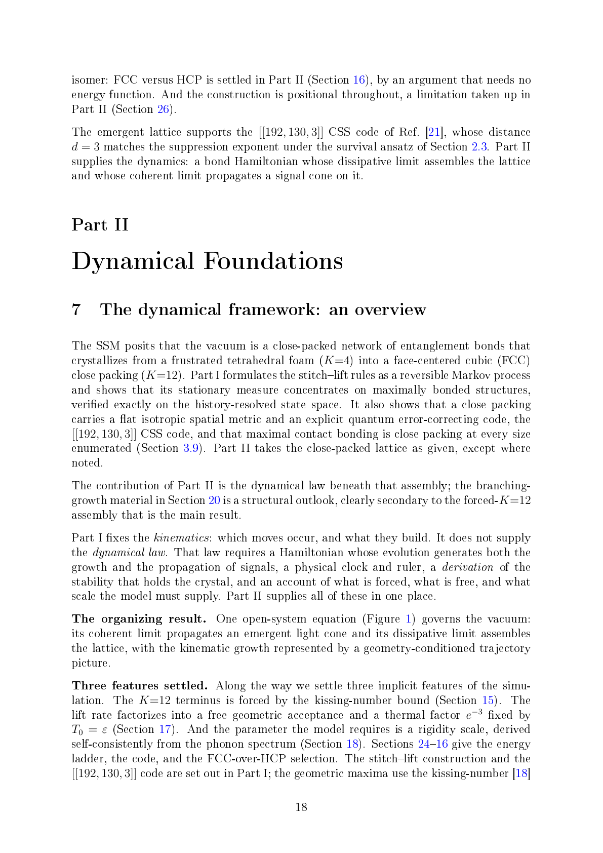
Figure 4: Growth of a patch. (a, b) Vertical sections (0 ≤ x < 0.9L) through 64 × 64 slabs, colored by
stacking variant. (a) The two twin variants ABC and ACB start mixed and coarsen until one dominates.
(b) A tilted grain (black, off the substrate’s layer heights) nucleates near layer 150 and takes over. (c) Mean
twin imbalance against height for three slab widths, 16 runs each; shading is the standard error.
the three slabs checked; a fourth, taken over by a tilted grain, is left out. This is the same signal
as the deep bins of Table 12. The excess is positive in every slab, with both lift orientations, so
it is tied to the growth direction rather than the lift orientation. We have not found its cause. It
may come from a defect that forms at the growth front, or from misclassified tetrahedra next to
defects. It should not be read physically until this is settled. In a defect-free FCC crystal the two
counts are equal by symmetry, so any asymmetry must sit in defects.
Table 12: Along-growth void bias (up−down)/total against depth below the outermost complete layer (6
slabs, 32 × 32 × 260, axis lift). Standard errors are 0.001–0.003 in the shallow bins and 0.0001 in the deep
ones.
Depth (gaps) 0–1 2–3 4–5 6–7 8–9 10–11 12–19 20–49 50–99 100–200
Bias +0.017 −0.001 −0.001 +0.002 +0.002 −0.002 0.000 −0.0003 −0.0004 −0.0006
7.5 Remnant trapping and matter–antimatter selection
Remnant nodes that settle on a one-way front are never trapped in a tetrahedral void that points
against growth. The void population itself is balanced, so any selection of one void class for matter
must come from trapping. Geometry suggests why. On a flat close-packed surface, a remnant can
rest only in a three-fold hollow, not on top of an atom. The hollows that the next layer covers
become tetrahedral voids whose apex points along the growth direction (Fig. 5a). We tested
whether this holds on rough, realistic fronts.
18
Model. A remnant is a sphere that must stay at least R =
p
3/8 L ≈ 0.612L from every
lattice node. This is its closest approach inside a void. At a random time t, we drop a remnant at
a random lateral position onto the surface formed by the first t nodes. It settles along −z, against
the growth direction, in small downward steps that push it out of contact, until it comes to rest.
The rest of the growth then runs unchanged, so the remnant acts as a passive tracer. We classify
its final site by the nodes within R + 0.04L. Three below and one above is a tetrahedral void
pointing along growth. One below and three above is a tetrahedral void pointing against growth.
Three below and none above is the open hollow, which becomes the octahedral side. Anything else
is irregular. A later node closer than R − 0.04L would mark a conflict, where the remnant would
have blocked growth.
Validation. On a perfect ABC crystal, we dropped 40 remnants onto the third layer. Of
these, 19 ended in voids along growth and 21 on the octahedral side. None ended against growth,
as the geometry requires.
Results. Each run used a 32 × 32 slab of 150 layers with 300 remnants, with four seeds per
lift orientation (Table 13, Fig. 5c). Of 2,400 remnants, 2,394 came to rest on three contacts in
a hollow, and 6 on two. No conflict occurred, so the passive-tracer approach is consistent. The
two lift orientations give the same result. Rough fronts, steps and twin boundaries produced no
trap pointing against growth. Seven remnants (0.3%) ended with one node below and two above.
This looks like a void pointing against growth with one node missing. We did not examine these
cases one by one. Even counting all seven as against growth, the fraction is at most 0.3%. The
split between along-growth voids (41%) and the octahedral side (59%) differs from the 50/50 of a
perfect surface; we have not analyzed why.
Table 13: Final sites of remnant nodes dropped onto one-way slabs.
Lift orientation Remnants Tet., along Octahedral side Tet., against Irregular
Axis 1,200 479 711 0 10
Both 1,200 498 698 0 4
Total 2,400 977 (41%) 1,409 (59%) 0 14 (0.6%)
The result confirms this geometric selection on disordered surfaces. It does not test the premise
behind it. The selection enters through the settling direction: the assumption that remnants arrive
from the growth side and rest on the front. Remnants might instead be overgrown from the side,
move by thermal motion or be captured from below. Whether they settle as assumed is a physical
assumption of the model.
7.6 How new sheets form
New sheets do not start from lifted nodes. They advance from step edges, mostly by stitching on
the triangles that join neighboring flat sheets. This carries the stacking order from one sheet to
the next.
We followed every new layer in one 32 × 32 and one 64 × 64 slab (99 layers each, axis lift;
Table 14). The front is rough, so it always has step edges where an island of the top sheet ends.
At such an edge, a triangle can have two corners on the island’s edge and one in the sheet below.
Stitching it across its top edge puts a node one layer higher, on the island (Fig. 6). That node’s
own triangle is then stitched across its slanted edge. This places the next node one bond along, so
a bonded row grows along the step. Triangles that bridge the row and the island add more rows.
Flat triangles form in the new sheet once two rows meet. New layers thus advance from step edges,
and their first in-sheet triangle appears only after most of the layer is placed. This is step-flow
growth. An interactive version of Fig. 6 is at https://raghu91302.github.io/ssmtheory/step_
edge_sheet.html.
This mechanism explains two earlier results. FCC does not depend on the lift rate (Section 6.3),
19
surface layer, top view
(growth
ˆ
g
out of page)
covered hollow tet. void along
ˆ
g
open hollow octahedral side
atop a surface atom: not held
atom of the next layer (dashed)
0 1
2 3
4 5
6 7
8 9
10 11
12 19
20 49
50 99
100 200
depth below the front (layer gaps)
1.0
0.5
0.0
0.5
1.0
1.5
2.0
2.5
3.0
along-growth void bias (%)
b
one-way slab (6 runs)
tet.,
along
oct.
side
tet.,
against
irreg.
0
200
400
600
800
remnant nodes
0 of 2,400
c
final site of 2,400 remnant nodes
one lift orientation
lift both directions
a
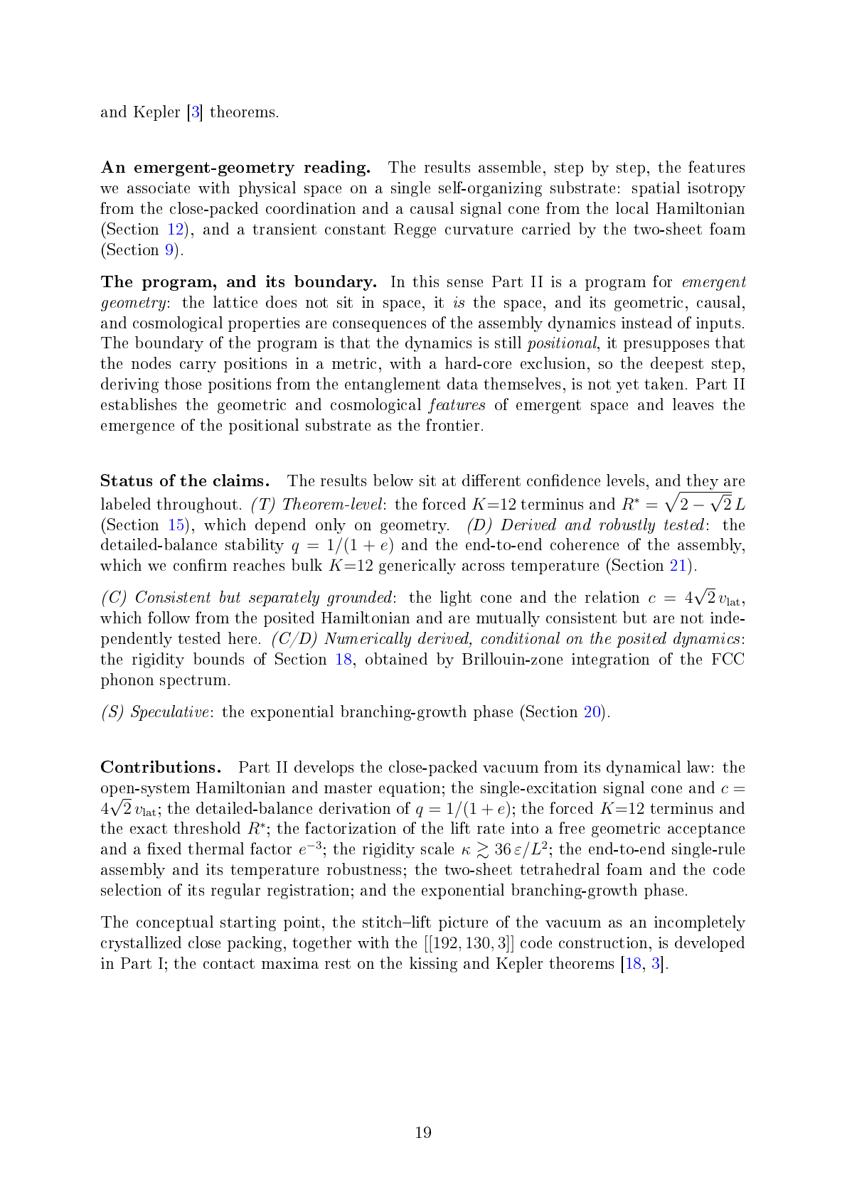
Figure 5: Void classes and remnant trapping. (a) Top view of a growing (111) surface. A remnant node
can rest in either three-fold hollow but not atop an atom; the hollows that the next layer covers become
tetrahedral voids pointing along the growth direction ˆg, and the others become the octahedral side. (b)
Along-growth bias of the void population against depth below the front in one-way slabs: confined to the
outermost layers. (c) Final sites of 2,400 remnant nodes dropped onto one-way slabs: none ends in a
tetrahedral void pointing against growth.
because sheets are not made by lifts. And twin domains form because a layer advances from many
step edges at once. Each edge grows on its own, and the regions meet at twin boundaries.
Table 14: How layers start in a growing patch (one slab per width).
32 × 32 64 ×64
Layers whose first node was made by a lift 2% 1%
Lifted nodes per layer ≈ 6 of 1,024 ≈ 24 of 4,096
Placements before the layer’s first in-sheet triangle ≈ 650 (0.6 layer) ≈ 2,900 (0.7 layer)
7.7 Why the stacking is ABC
The geometry of stitch forces the stacking. Stitch is a point inversion, and FCC is the only close-
packed stacking that stays intact under it. So every node that stitch adds from triangles on one
FCC lattice lies on that lattice, and only lift can create another stacking.
Stitch is a point inversion. For an equilateral triangle with corners a, b and c, the stitch
apex across edge ab is
x = a + b − c. (6)
This is the corner c reflected through the midpoint of the edge. The simulation places the apex
at (
√
3/2)L from the edge midpoint. For an equilateral triangle this is the same point, and the
unit-bond condition keeps triangles equilateral.
FCC is closed under it. Other stackings are not. FCC is a Bravais lattice, so every node
is a lattice point; hcp is not, as Ref. [2] also notes. For any three nodes, the point a + b −c is then
a lattice point too. Among all stackings of close-packed sheets, ABCABC. . . is the only Bravais
lattice. ABAB. . . (hcp) and all other stackings have more than one node per primitive cell, and
20
a triangle between two flat sheets b stitch places one node a layer higher
c the next node, one bond along the step
d a second row: flat triangles form
lower sheet upper sheet (island) triangle being stitched new sheet
Figure 6: How a new sheet starts at a step edge. All sheets are flat. (a) At the edge of an island of the
upper sheet, a triangle (amber) has two corners in the upper sheet and one in the lower sheet. (b) Stitching
it across its top edge places a node one layer higher. (c) That node’s own triangle is stitched across its
slanted edge, placing the next node one bond along the step; repeating this lays a bonded row. (d) Triangles
bridging the row and the island add a second row, and the two rows bond into flat triangles of the new
sheet.
for them a + b − c can fall off the structure. Consider a step edge (Fig. 6a,b), with b
1
and b
2
in
sheet B and a in sheet A below. The new node b
1
+ b
2
− a lies two layers above A. It sits over
the hollow of sheet B that is not above a node of A. This is the C position. ABA would need the
new node directly above a, and no stitch can put it there.
One tetrahedron fixes the lattice. The three edge vectors at a corner of a regular tetra-
hedron are primitive vectors of the FCC lattice. Once a lift makes one tetrahedron, every node
that stitch adds from it lies on that FCC lattice. The stacking along each close-packed direction
is then ABC. It is ACB, the mirror twin, if the first lift went to the other side of its triangle.
Only lift leaves the lattice. Each triangle within a sheet has two lift apices. One is a lattice
site, and the other is the matching site of the mirror twin. A lift on the second side starts a twin
or a stacking fault. A lift on a between-sheet triangle can start a grain with a different orientation.
The two competing hollow positions above a sheet are L/
√
3 apart. With r
ex
> L/
√
3, exclusion
lets only one of them be filled. This is the lower edge of the exclusion plateau in Section 6.4.
Consequences. The rule explains three earlier results. The hcp fraction grows with the lift
rate (Section 6.3). A patch grows as twin domains, because its flat starting sheet fits both twins;
each first lift picks one, and stitch then carries it forward. Finally, the exclusion radius must exceed
L/
√
3.
Numerical check. We recorded the triangle each node was built on. We then tested every
placement against the FCC lattice set by the seed triangle and the first lift, in six clusters of
N = 10
5
(Table 15). There were 485,073 stitches built on triangles lying fully on the lattice. All
but 17 (0.004%) landed on the lattice. All 17 were in one high-lift run, and we have not traced
21
them. Lifts from such triangles left the lattice 20–29% of the time. Raising the lift weight to 0.2
raised these off-lattice lifts about eightfold on average (six- to ninefold, seed by seed) and the bulk
hcp fraction about sevenfold (six- to elevenfold). In seed 2, a large part of the cluster lies off the
seed lattice. It belongs to a twin grain started by an early off-lattice lift.
Table 15: Placements tested against the seed’s FCC lattice (N = 10
5
).
w Seed On seed lattice Stitches from on-lattice triangles Of these off Lifts on / off Bulk hcp
0.0225 0 0.994 98,761 0 526 / 135 0.0009
0.0225 1 0.989 98,115 0 469 / 163 0.0011
0.0225 2 0.618 47,367 0 229 / 92 0.0018
0.0225 3 0.992 98,567 0 496 / 130 0.0009
0.2 0 0.861 78,678 17 3,464 / 1,163 0.0101
0.2 1 0.745 63,585 0 2,831 / 934 0.0071
8 Results III: quantum structure of the grown network
The SSM reads every bond as a Bell pair. The simulation evolves no quantum state, but two
quantum objects are defined by the bond graph alone. One is the network of Bell pairs itself. The
other is the FCC stabilizer code of Ref. [7], which puts one qubit on every bond. Section 8.2 shows
that they are related by one local operation: Bell pairs checked by one parity measurement per
node form a code state on one qubit per bond. Both are stabilizer states or codes [37, 38, 39].
They depend only on which nodes are bonded, so the grown graph fixes them. Their defects are
the crystal’s defects. This section measures both on the grown networks. Everything here is an
exact property of states defined on the graph. Nothing is time-evolved, and we do not model noise.
8.1 Bell pairs and the area law
Give each bond two qubits, one at each end, in the Bell state |Φ
+
⟩ = (|00⟩+|11⟩)/
√
2. The network
state is then a product of Bell pairs. Take any region A of nodes. A bond with both ends in A,
or both outside, adds nothing to the entanglement between A and the rest. A bond that crosses
the boundary leaves one qubit in A in a maximally mixed state. So the entanglement entropy is
exactly
S(A) = |∂A| ln 2, (7)
where |∂A| is the number of bonds that cross the boundary. This is an area law [40], and its
coefficient is the number of bonds crossing unit area. Ideal FCC has 6
√
2 bonds per L
3
. A bond of
length L crosses a randomly oriented plane with probability proportional to |cos θ|, whose mean
is 1/2. A randomly oriented surface is therefore crossed by 3
√
2 ≈ 4.243 bonds per L
2
. A (111)
plane is crossed by three bonds per node and 2/
√
3 nodes per L
2
, giving 2
√
3 ≈ 3.464 bonds per
L
2
.
We counted the bonds crossing spheres about the center of four clusters of 10
5
nodes, for radii
from 4L to 16L (Fig. 7b). Above R = 8L the count per unit area is 4.14 ± 0.03, with a spread
over seeds from 4.06 to 4.18. The ideal value is 3
√
2 = 4.243, and ideal FCC balls cut in the
same way give 4.23–4.24. The grown network thus has an area law with a coefficient about 2.5%
below the ideal one. In patches we counted bonds crossing horizontal planes between layers (four
48 × 48 slabs, 80 planes each). The mean is 3.268 ± 0.003 per L
2
, 5.7% below 2
√
3 (Fig. 7c).
The deficit has a simple source. Each missing node removes the bonds it would have had. In the
analyzed patch region 2.7% of lattice sites are empty, mostly at twin boundaries (Section 7). A
missing node also leaves its neighbors under-coordinated, so the bond deficit is about twice the
vacancy fraction. Grain boundaries and vacancies do the same in clusters on a smaller scale. The
entanglement density of the network is therefore a direct measure of its defects. These counts
22
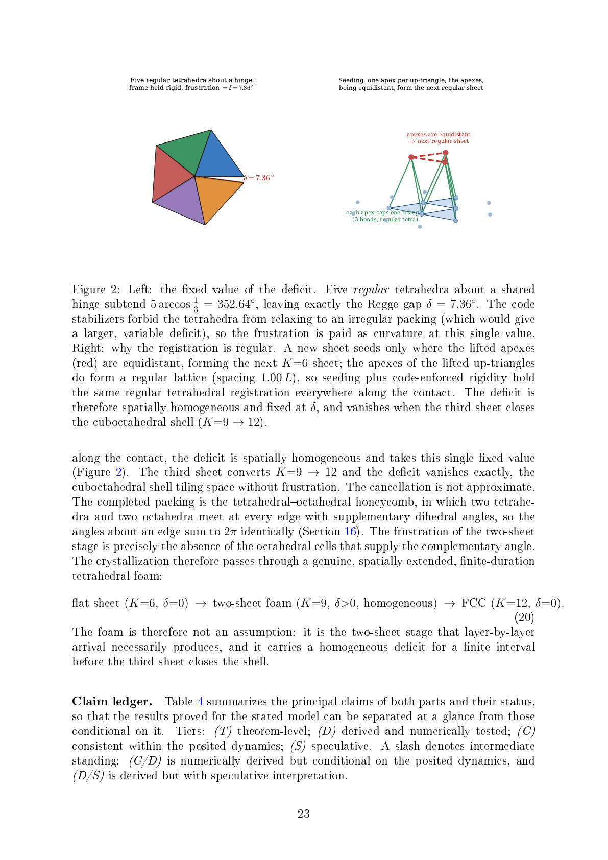
are for the Bell pairs alone; the node checks of Section 8.2 lower the entropy of each such region
by exactly ln 2 when the region and its complement are both connected, and leave the per-area
coefficient unchanged.
8.2 From Bell pairs to edge qubits
The Bell-pair network of Section 8.1 has two qubits per bond, one held by each end node. The
code of Section 8.3 has one qubit per bond. We now show that the second is obtained from the
first by one local operation at each node: a parity check on the node’s own qubits.
Each Bell pair is one edge qubit. Label the two virtual qubits of bond e = (u, v) as a
e,u
and a
e,v
. The Bell state |Φ
+
⟩ lies in the two-dimensional subspace with Z
a
e,u
Z
a
e,v
= +1, spanned
by |00⟩ and |11⟩. Define the isometry V
e
: |0⟩ 7→ |00⟩, |1⟩ 7→ |11⟩. On this subspace an edge qubit
has the operators
¯
Z
e
= Z
a
e,u
= Z
a
e,v
,
¯
X
e
= X
a
e,u
X
a
e,v
, (8)
and |Φ
+
⟩ = V
e
|+⟩. The Bell-pair network is therefore
N
e
V
e
|+⟩: a product state of edge qubits,
each in |+⟩.
Each node checks its own bonds. Let node v apply the projector
P
v
=
1
2
1 +
Y
e∋v
Z
a
e,v
, (9)
which acts only on the qubits that v holds. Under the isometry,
Q
e∋v
Z
a
e,v
=
Q
e∋v
¯
Z
e
= A
v
, the
Z check of node v in Section 8.3. So
|Ψ⟩ ∝
Y
v
P
v
O
e
|Φ
+
⟩ =
O
e
V
e
Y
v
1
2
(1 + A
v
) |+⟩
⊗N
E
, (10)
where N
E
is the number of bonds.
Result. |Ψ⟩ = (
N
e
V
e
)|ψ
G
⟩, where |ψ
G
⟩ is the edge-qubit stabilizer state with checks A
v
on
every node and
Q
e∈C
¯
X
e
on every closed loop C. In the Z basis it is the equal superposition of
all sets of bonds that meet every node an even number of times. Proof. |+⟩
⊗N
E
is stabilized by
every
¯
X product. Such a product commutes with all A
v
exactly when it meets every node an even
number of times, that is, when it is a product over loops; these survive the projection, and the A
v
are added. With N
V
nodes and N
E
bonds on a connected graph this gives N
V
− 1 independent
node checks and N
E
− N
V
+ 1 independent loops, N
E
in all, so |ψ
G
⟩ is a single pure state. It
is nonzero, since the empty set of bonds has amplitude 2
−N
E
/2
in P
+
|+⟩
⊗N
E
. For the triangle,
|ψ
G
⟩ = (|000⟩ + |111⟩)/
√
2, the GHZ state of Section 2.4. The two readings used in this paper
are thus related by the node projections: the checked Bell-pair network is the code state, written
with two virtual qubits per bond. The Bell pairs are the resource. After the checks each bond
keeps Z
a
e,u
Z
a
e,v
= +1, so its two qubits are perfectly correlated, but they are no longer a Bell
pair: for the triangle, each bond’s two qubits are an equal classical mixture of |00⟩ and |11⟩. The
entanglement has become shared around loops. Across any cut it still amounts to one ebit per
crossing bond, less one (see below). We confirmed this directly for the triangle, and checked purity
on random graphs and on a grown cluster.
Relation to the FCC code. |ψ
G
⟩ satisfies every node check and every octahedral loop check,
so it is a code state of the FCC code. It is the particular code state in which the remaining loops,
such as single triangles, also take the value +1. Those loops are logical X operators of the code,
so the node projections prepare one definite codeword, with every logical qubit fixed.
Preparation as a physical process. The projectors P
v
are not unitary. Applying them by
post-selection, keeping only runs in which every node finds parity +1, succeeds with probability
2
−(N
V
−1)
, which is exponentially small. A deterministic protocol avoids this. Every node measures
its parity, and the outcomes are then repaired by
¯
X strings. Write the outcome of node v as s
v
= ±1
and the set of nodes with s
v
= −1 as D.
23
Proposition (deterministic preparation). On a connected graph:
(i) Every outcome pattern that can occur has |D| even, and every such pattern can be repaired:
there is a set of bonds T whose odd-degree nodes are exactly D, and applying
¯
X
T
=
Q
e∈T
¯
X
e
removes every −1.
(ii) Every step preserves the encoded Bell-pair subspaces: the state keeps Z
a
e,u
Z
a
e,v
= +1 on
every bond throughout.
(iii) For every outcome pattern, the repaired state is exactly (
N
e
V
e
)|ψ
G
⟩, with no phase, and it
does not depend on which repair set T is chosen.
Proof. (i) On the Bell-pair subspaces,
Q
v
A
v
=
Q
e
¯
Z
2
e
= 1, so the outcomes multiply to +1
and |D| is even. Pair the nodes of D arbitrarily and join each pair by a path of bonds, which exists
because the graph is connected. Let T be the set of bonds used an odd number of times. A path
has odd degree only at its two ends, and degrees add modulo 2, so the odd-degree nodes of T are
exactly D. Since
¯
X
e
anticommutes with A
v
exactly when v is an end of e,
¯
X
T
anticommutes with
A
v
exactly when v ∈ D, and so turns every s
v
= −1 into +1. (ii) Each parity measurement is a
product of Z operators, and each
¯
X
e
= X
a
e,u
X
a
e,v
; both commute with every Z
a
e,u
Z
a
e,v
. (iii) Write
P
s
=
Q
v
1
2
(1 + s
v
A
v
). The state after measurement is P
s
|+⟩
⊗N
E
/
√
p
s
. Because
¯
X
T
flips exactly
the A
v
with v ∈ D,
¯
X
T
P
s
= P
+
¯
X
T
, where P
+
is the all-+1 projector. And
¯
X
T
|+⟩
⊗N
E
= |+⟩
⊗N
E
.
Hence
¯
X
T
P
s
|+⟩
⊗N
E
= P
+
|+⟩
⊗N
E
for every allowed s. Taking norms, all allowed patterns have the
same probability; there are 2
N
V
−1
of them and their probabilities sum to 1, so p
s
= 2
−(N
V
−1)
, and
the repaired state is P
+
|+⟩
⊗N
E
/
√
p
+
= |ψ
G
⟩ exactly. Two repair sets with the same odd-degree
nodes differ by a set of bonds of even degree everywhere, which is a product of loops and fixes
|ψ
G
⟩ with eigenvalue +1. □
Physically, each node measures the parity of the qubits it holds, and each correction
¯
X
e
is one
single-qubit X gate at each end of a bond. The only non-local resource is classical: the outcomes
must be communicated so that defects can be paired. Pairing nearby defects, for example by
minimum-weight matching, keeps the strings short, but any pairing gives the same state by (iii).
The corrections can also be left unapplied and tracked as a known Pauli frame. We checked all three
properties with explicit state vectors on the two virtual qubits of every bond, for every allowed
outcome pattern on three small graphs (the triangle, K
4
and a five-node graph with a chord). This
is the repair step of a Z
2
gauge theory, and it is the node-level checking of Section 2.2 written as
an operation: random outcomes, repaired locally, always give the same state. Preparation is not
yet persistence. The proposition shows that one round of checking and repair reaches the target
state from any outcome. Persistence also needs the state to be kept under continuing disturbance,
which requires a specified dynamics of repeated verification and repair together with a noise model.
That dynamics, and the threshold below which it keeps the lattice, is not given here.
Entanglement after the checks. For a region A of nodes, with n
A
and n
B
connected
components of A and of its complement, the checked state has
S(A) =
|∂A| − n
A
− n
B
+ 1
ln 2. (11)
Each connected component’s product of node checks fixes the parity of the bonds it shares with
the cut, and these parities give n
A
+ n
B
− 1 independent constraints on the |∂A| crossing pairs.
For a connected region with a connected complement, such as the spheres and slabs of Section 8.1,
S(A) = (|∂A|− 1) ln 2. The area-law coefficient of Section 8.1 is unchanged, and the checks lower
the entropy by one constant ln 2, the topological entanglement entropy of a Z
2
gauge theory [41, 42].
We confirmed the formula exactly, by stabilizer ranks over GF(2), for 75 regions on random graphs,
the octahedron and a grown cluster of 300 nodes.
24
8.3 The FCC stabilizer code on the grown graph
The code. Ref. [7] defines a CSS code on ideal FCC. It is built like the toric code [43], with qubits
on bonds and checks on nodes and voids. A qubit sits on every bond. Each node carries a Z check,
the product of Z over its 12 bonds. Each octahedral void carries an X check, the product of X
over the 12 bonds among its six corner nodes. On a periodic cube of side ℓ (in units of L/
√
2, so
with ℓ
3
/2 nodes and 3ℓ
3
bonds) the code has k = 2ℓ
3
+ 2 logical qubits, [[192, 130, 3]] at ℓ = 4. We
build the same checks on the grown graph: a Z check on every node, over the bonds it actually has,
and an X check on every complete octahedron, six nodes joined by all 12 octahedral bonds. We
find octahedra as pairs of nodes
√
2L apart whose four common neighbors form a bonded square.
Our rank code reproduces k = 130 and k = 434 for the ideal codes at ℓ = 4 and 6.
The checks always commute. An X check and a Z check overlap on the bonds of the
octahedron that meet the node. Each corner of a complete octahedron meets exactly four of its
twelve bonds, and every other node meets none. The overlap is always even, so H
X
H
T
Z
= 0 over
GF(2) on any graph the rules can grow. We confirmed this numerically for 2 × 10
4
octahedra in
each run, and for every check in the patches whose exact parameters are given below. Defects
remove checks, but they never make the code invalid.
What a defect does. In ideal FCC every node has 12 bonds and is a corner of 6 complete
octahedra, and every bond lies in 2 of them. We call a node code-perfect when it has 12 bonds, 6
complete octahedra and 8 bonded tetrahedra, as in ideal FCC (in our data the first two conditions
imply the third). A bond is exposed when it lies in no complete octahedron. A Z error on an
exposed bond commutes with every X check and goes undetected. It is not a stabilizer either. A
product of Z checks over a set of nodes is Z on the bonds leaving that set, so a single bond is
a stabilizer only if it is a bridge of the graph. The grown graph has no bridge, because the seed
triangle (or the starting sheet of a patch) has none, every new node closes a triangle when it joins
(Section 2.5), and bonds are never removed. Where exposed bonds occur, the code as grown has
distance 1. Every exposed bond still lies on some loop, so adding such loops as X checks would
detect these errors, at the cost of logical qubits; with every loop as a check the code would encode
none (Section 2.4). The positions of exposed bonds are known from the graph, so they could also
be removed or treated as gauge qubits. We do not analyze these options here.
Clusters. Table 16 gives the results for two regions. The first is a structural interior, nodes
at depth 3 or more (one layer shallower than the depth 4 used in Section 6). It leaves out the
surface and the surroundings of vacancy pockets, so it gives the favorable figure. The second is
purely geometric, the ball within 0.8 times the median node radius, which keeps every defect. At
the geometric lift weight, 96.3% of interior nodes are code-perfect and 0.15% of interior bonds are
exposed. In the geometric region these become 89% and 1.1%, with a large spread over seeds. The
spread comes from twin grains started by early off-lattice lifts (Section 7.7). Seed 2, which has a
large twin grain, has the lowest values. Raising the lift rate degrades the interior code steadily
(Fig. 7a). The region values are noisier and flat between δ = 0.022 and 0.05.
Patches. The code in a young patch is dominated by twin boundaries. In 48 ×48 slabs of 100
layers, 76% of nodes in the geometric region (layers 3 to about 85) are code-perfect, the region
has 86% of the ideal number of X checks, and 3.3% of bonds are exposed. The code heals as the
patch grows. In two 32 ×32 slabs of 300 layers, the number of X checks per lattice site rises from
0.68 in the first ten layers to 0.85–0.90 near layer 70 and to 0.93–1.00 above layer 200, as one twin
variant takes over (Section 7).
Exact code parameters. For a direct count we cut four 16 × 16 patches flat after 12 layers
and computed the ranks of H
Z
and H
X
over GF(2). Bonds are taken as all node pairs within r
b
,
which is the simulator’s bonding rule. Table 17 gives the results. Each grown patch is compared
with a perfect ABC patch of the same size and shape. Defects, mostly twin boundaries, remove
4–8% of nodes and 22–39% of X checks. All remaining X checks are independent, as in the perfect
patch. The number of logical qubits per physical qubit rises slightly, from 0.667 to 0.679–0.690.
25
Table 16: The FCC stabilizer code on grown networks (N = 10
5
clusters with the unit-bond condition;
patches 48 ×48 ×100). Interior: depth ≥ 3. Region: the ball within 0.8× the median node radius (clusters),
or from layer 3 up to 8 layers below the 90th height percentile (patches). X checks are per lattice site of
ideal FCC, which has one. Values are means over the number of seeds in brackets.
Lift fraction Code-perfect nodes Exposed bonds X checks
interior region interior region per site (region)
Clusters, δ = 0.011 (4) 0.0015 0.991 0.978 0.0004 0.0015 0.989
Clusters, δ = 0.022 (4) 0.0030 0.978 0.893 0.0009 0.014 0.937
Clusters, δ = 0.05 (4) 0.0065 0.963 0.891 0.0015 0.011 0.940
Clusters, δ = 0.10 (4) 0.0129 0.935 0.820 0.0028 0.018 0.903
Clusters, δ = 0.20 (4) 0.0256 0.891 0.750 0.0045 0.024 0.867
Patches, δ = 0.05 (4) 0.0067 0.957 0.764 0.0016 0.033 0.858
The higher rate is not a gain. The number of logical qubits itself falls, and wherever a bond is
exposed the code has a weight-1 logical operator. We did not compute code distances of these
patches. At w = 0.005, under a quarter of the geometric weight, the patch still loses 27% of its X
checks. Single seeds at other weights thus suggest that the loss in young patches is set mainly by
twin boundaries rather than by the lift rate.
Table 17: Exact parameters of the FCC code on 16 × 16 patches cut after 12 layers, against a perfect
ABC patch of the same shape (periodic in x and y, open at top and bottom). n: physical qubits (bonds);
k = n − rank H
Z
− rank H
X
.
Patch Nodes n X checks rank H
X
k k/n
Perfect ABC 3,072 17,664 2,816 2,816 11,777 0.667
Grown, seed 0 2,834 14,659 1,716 1,716 10,110 0.690
Grown, seed 1 2,889 15,363 1,985 1,985 10,490 0.683
Grown, seed 2 2,894 15,428 2,006 2,006 10,529 0.682
Grown, seed 3 2,940 15,997 2,202 2,202 10,856 0.679
Grown, seed 0, w = 0.005 2,904 15,552 2,051 2,051 10,598 0.681
Grown, seed 0, w = 0.09 2,802 14,279 1,619 1,619 9,859 0.690
8.4 Bond tolerance and code quality
The bond tolerance δ enters the quantum structure only through the lift rate, w = (
√
2/π)δ
(Section 4). Lifts on the twin side of a triangle start twins and grains, and these remove checks
and expose bonds. Table 16 and Fig. 7a give the result. In clusters, over δ = 0.011 to 0.20,
the fraction of interior nodes that are not code-perfect rises from 0.9% to 10.9%, so a tighter
bond tolerance gives a cleaner code. In young patches the twin boundaries dominate instead
(Section 8.3). We do not convert δ into a Bell-pair fidelity. That needs a physical model of how a
stretched bond loses entanglement, which the SSM does not yet supply.
26
1 2
realized lift fraction (%)
0.000
0.025
0.050
0.075
0.100
0.125
0.150
fraction of interior
a
nodes not code-perfect
exposed bonds (
£
10
)
5 10 15
sphere radius
R
(
L
)
3.4
3.6
3.8
4.0
4.2
4.4
4.6
bonds cut per area (
L
¡
2
)
ideal FCC
3
p
2
b
0 1 2 3
patch (seed)
2.8
3.0
3.2
3.4
3.6
bonds cut per area (
L
¡
2
)
ideal (111)
2
p
3
c
0.05 0.10 0.20
±
2.4
2.6
2.8
3.0
S=A
(nats per
L
2
)
Figure 7: Quantum structure of the grown network. (a) Fraction of interior nodes that are not code-
perfect and fraction of exposed interior bonds (×10; a Z error there goes undetected) against the realized
lift fraction, N = 10
5
, mean over 4 seeds; the top axis gives the bond tolerance δ. (b) Bonds crossing a
sphere of radius R per unit area in four clusters; with one Bell pair per bond the entanglement entropy per
unit area is this number times ln 2 (right axis). Dashed: ideal FCC, 3
√
2. (c) Bonds crossing (111) planes
per unit area in four 48 × 48 patches (mean of 80 planes, bars: standard deviation); dashed: ideal, 2
√
3.
9 Robustness
The main results hold across kinetic schemes (below), lift orientations (Sections 6.6 and 7.1), the
unit-bond condition, the structure classifier and the bonding radius. Appendix B compares the
present code with that of [2].
Kinetic scheme. The site-weighted and legacy rules give the same FCC fraction at the same
realized lift fraction, over the full range (Fig. 3a).
Unit-bond condition. We regrew the four N = 10
6
clusters of Section 6 with the condition.
In every seed it lowers the interior (depth ≥ 4) FCC fraction from 98.6% to 98.0%. The mean
bulk FCC fraction changes from 0.943 to 0.939, and bulk hcp from 0.0008 to 0.0011. The effect
is small and systematic, and no conclusion changes. Without the condition, the median error in
bond length grows from 10
−15
at radius 10L to 10
−8
at 60L, far below the 5% tolerance. Clusters
several times larger would need the condition.
Structure classifier. Reclassifying one N = 10
6
cluster with CNA cutoffs of 1.15L, 1.207L
and 1.25L gives identical fractions. At 1.30L the bulk FCC fraction changes only in the sixth
decimal place.
Bonding radius. At N = 3 × 10
4
(4 seeds each, with the unit-bond condition), bulk FCC
is 0.914, 0.915, 0.925 and 0.917 for r
b
= 1.02L, 1.05L, 1.08L and 1.10L. All agree within one
standard error (0.010–0.016).
Not yet tested. A different seed shape, such as a tetrahedron, and a finer r
ex
sweep near
L/
√
3. Section 2 argues that the triangle is the natural seed, but the simulations do not test
whether the bulk results depend on it.
10 Discussion
What the results show. The SSM rules select FCC over a wide range of settings. Bulk FCC
exceeds 90% for realized lift fractions below about 1%. It holds across the exclusion plateau from
0.58L to 0.98L, for three lift orientations and two kinetic schemes. hcp and icosahedral order are
27
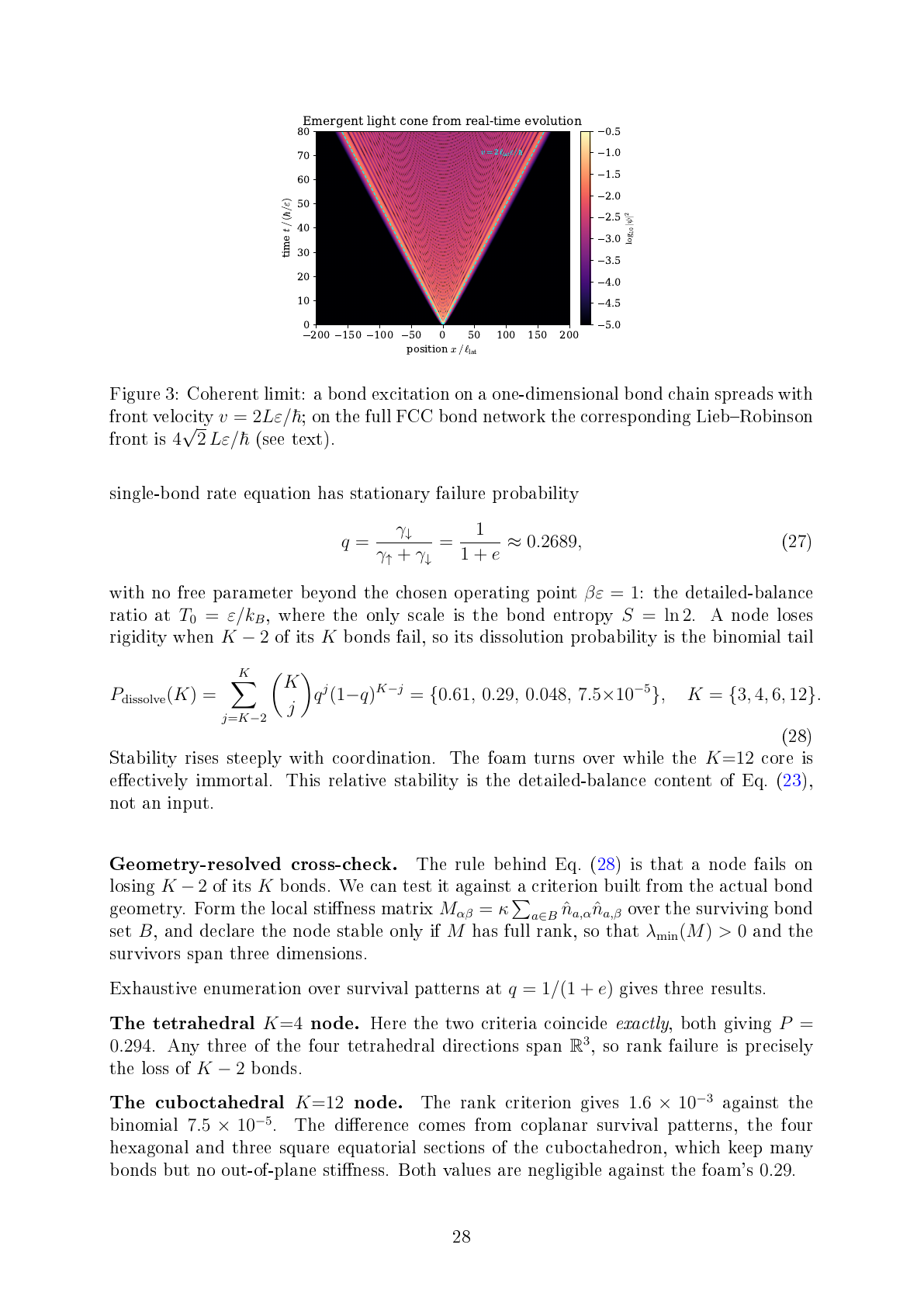
almost absent. Sequential deposition of hard spheres behaves differently and gives random close
packing with polytetrahedral order [44]. The difference lies in the operators. Stitch and lift place
nodes only at close-packed positions next to an existing triangle, so close packing is built into the
rules. The stacking is not put in by hand, but it is forced. Stitch is a point inversion through a
bond midpoint, and FCC is the only close-packed stacking closed under it. So every node that
stitch adds from triangles on one FCC lattice stays on it, and only lift can create hcp, twins and
misoriented grains (Section 7.7). The lift rate needs no fitted value. Geometry predicts that lift is
suppressed by one power of δ. This gives a few percent for δ between about 2% and 5%, and any
rate in that range gives FCC.
What the results do not show. The network as a whole does not pass through a K = 4
phase. Locally, each lift makes a tetrahedral K
4
unit, and these units carry growth into three
dimensions. The tetrahedron is the natural local step between a sheet and the bulk. But co-
ordination 4 is neither common nor lasting. Only a third of nodes ever have it, they leave it
as fast as any other value, and the tetrahedral content never exceeds that of FCC. The sequence
K = 6 → K = 4 → K = 12 of Ref. [2] (sheets, then tetrahedra, then FCC) holds as a local docking
step, not as a global stage. If the SSM needs a global K = 4 phase, that phase is an assumption
about the initial state. A rule set that produces it would be a separate test, for example lift-first
growth or a high early lift rate that falls off. The value e
−3
has no special status. As a per-step
probability it gives about 1% realized lift and 91% FCC, slightly below the values at rarer lift.
The bare rule also cannot keep long-range order. Position noise ε would destroy order after about
ln(δ/ε)/ ln 1.3 layers, or about 15 layers for ε = 10
−3
. The unit-bond condition is therefore part of
the model. It is the most direct form of the Bell-pair rule in the simulation. More generally, the
model is pure geometry. It has no energetics, no thermal motion and no motion of remnant nodes.
A patch of the universe. A global lift orientation leaves no trace on the crystal. Twin
coarsening, though, provides a spontaneous symmetry-selection mechanism in finite patches. A
patch starts with both mirror variants and develops single-variant domains whose width grows
roughly as height
0.6
. If the SSM gives the two twin variants a physical meaning, this is a way for
large regions to share one variant without a global bias. In [2], the two orientations of tetrahedral
voids stand for matter and antimatter, and the observed excess of matter is attributed to a local
excess of one orientation. They are balanced in any FCC crystal by symmetry, and in the simulation
they are balanced to within about 2 × 10
−3
below the outermost layers. So selection of one class
for matter must come from trapping. On a one-way front, remnants that settle on the surface are
never trapped in tetrahedral voids pointing against growth (Section 7.5). A patch would then hold
only one class: matter and no antimatter. This is the local excess that [2] requires. On a front that
grows outward, “along growth” means outward everywhere, so every patch would select the same
class relative to its own growth direction. The simulation confirms the geometry of this selection,
but not the settling premise. The small excess of down tetrahedra points against growth. At a
few parts in 10
4
, it is too small to affect this.
Before the seed. Section 2 is the paper’s least secure part and is meant to be read that way.
Its exact core is small but useful: with one qubit per bond, the triangle is the smallest network
whose node and loop checks detect every error on its bonds, and the octahedral checks of the FCC
code are built from triangles. The section also ties the proposal to the simulations. Persistence,
read as “random bonds survive only if they have one length and are checked”, is what the growth
rules do: they try sites at random, keep only bonds within tolerance, and create every bond on
a loop. They model the creation half of the mechanism; continued maintenance of the finished
lattice is not simulated. Under two stated premises, a closed world in a pure state and adjacency as
correlation, persistence provably excludes classical probability theory, because classical pure states
of composite systems carry no correlations. It does not yet single out quantum theory; that would
follow if persistence implied purification in full, together with the other five principles of Ref. [22].
The persistence principle itself is the paper’s foundational postulate, stated as such, and it does
not alone fix a mechanism or select quantum mechanics. The rest, from the postulate to the state
before the lattice, is a proposal.
28
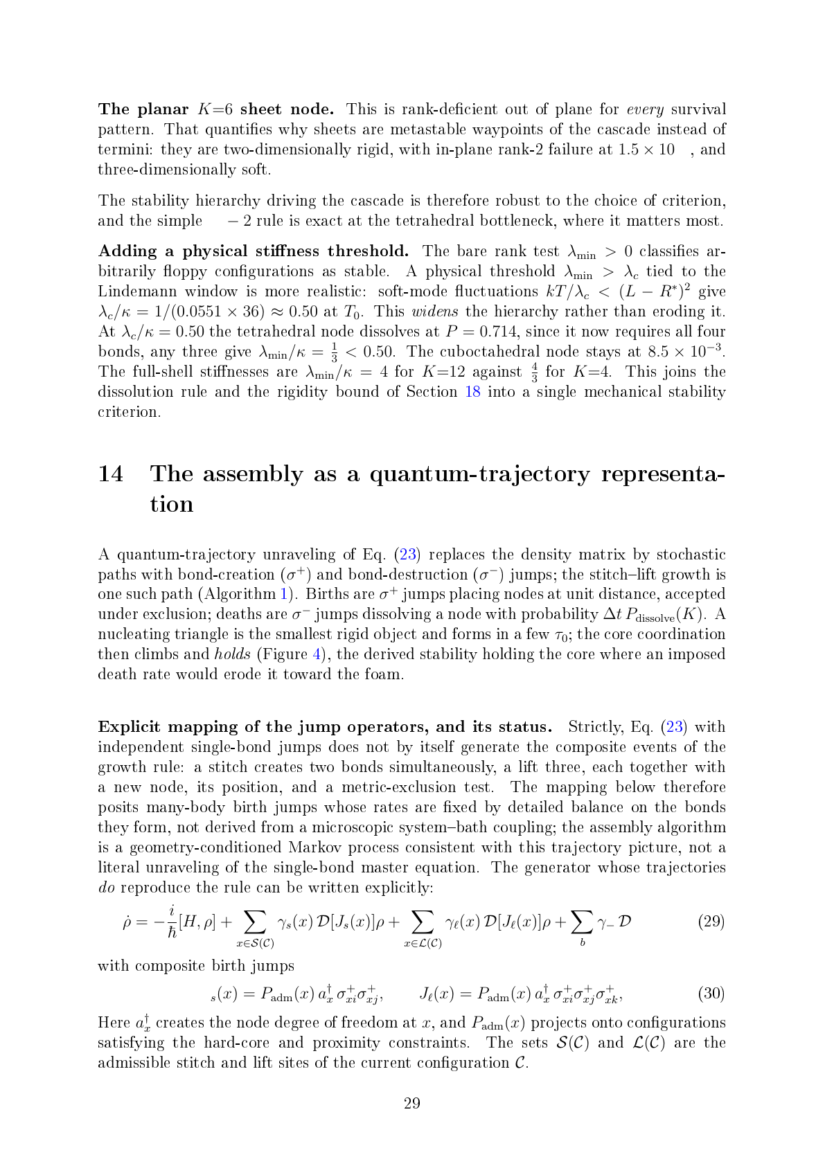
Quantum structure. Read as Bell pairs, the grown network is a quantum state whose
entanglement follows an exact area law. Its coefficient is the density of bonds crossing a surface.
Every missing node lowers it, so the entanglement density records the defects that growth leaves.
One parity check per node, acting only on qubits that node holds, turns the network into a code
state with one qubit per bond, so the Bell-pair and code readings are related by local operations.
The preparation is deterministic: random parity outcomes are repaired by local X gates along
paths, and every outcome gives the same state. The checks lower the entropy of a connected
region with a connected complement by exactly ln 2 and leave the coefficient unchanged. The
FCC stabilizer code [7] survives growth in a strong sense. Its checks commute on every graph
the rules can grow, because each corner of a complete octahedron meets an even number of its
bonds. Defects only remove checks. In the interior (depth ≥ 3, away from the surface and vacancy
pockets), about 96% of nodes carry the full structure of the ideal code; in a region that keeps every
defect, 89%. Two weaknesses remain. Exposed bonds, at 0.15% of interior bonds and about 1%
once boundaries are included, reduce the code distance to 1 where they occur. And twin boundaries
in young patches remove a large share of the X checks. Both are set by the growth rules. Exposed
bonds grow with the lift rate and hence with the bond tolerance δ, and twin boundaries become
sparser as domains coarsen. In the SSM picture, the error-correcting structure of space would thus
be imperfect where space is young and would improve as it grows. These results are exact for
the stabilizer states defined on the graph. They say nothing about how the state would evolve, or
about physical noise.
Open questions. (1) Whether remnants settle onto the front as assumed. This is the premise
behind the trapping result, and a model of remnant motion near the front would test it. (2) The
cause of the tetrahedron excess. Classifying the local setting of every unbalanced tetrahedron, and
testing the classifier’s tolerance, would settle it. (3) The nucleation rate and takeover criterion
of tilted grains. (4) The domain-growth exponent, from slabs wider than 64. (5) The off-lattice
lift rate. Section 7.7 traces stacking disorder to lifts on the twin side of a triangle. A model of
how often such lifts succeed, given exclusion by nearby nodes, would turn the measured 20–29%
into a prediction. (6) A formal version of the persistence principle of Section 2, a justification of
premises (P1) and (P2), and whether persistence implies purification in full, which with the other
five principles of Ref. [22] would select quantum theory. (7) A dynamics of repeated verification
and repair under noise, which would turn the one-round preparation of Section 8.2 into persistence,
and its threshold. (8) Whether exposed bonds can be handled as gauge qubits.
11 Conclusions
We propose that the lattice began from a state with no space, time or energy ledger, that persis-
tence, in a closed world where adjacency is correlation, excludes classical probability theory (an
exact result; it does not yet single out quantum theory), and that space is created and maintained
by one uniform probabilistic mechanism: random entanglements persist only as checked bonds of
one length. The first lasting structure was a triangle of bonds. With one qubit per bond, the
triangle is the smallest network whose node and loop checks detect every error on its bonds; its
checks fix a GHZ state, and each X check of the FCC code is a sum of four triangular loops.
From that seed, the SSM growth rules crystallize into FCC, and the FCC stacking is forced, not
just observed. Stitch is a point inversion through a bond midpoint, and only the FCC stacking
is closed under it, so only lifts can create other stackings. At 10
6
nodes, about 98% of interior
nodes are FCC (98.6% with the bare rule and 98.0% with the unit-bond condition, counting all
nodes at depth 4 or more). New sheets grow from step edges by stitching on the triangles that
join neighboring flat sheets, and this carries the stacking from sheet to sheet.
In a patch that grows one way, the void population is balanced: the two classes of tetrahedral
void agree to within about 2 ×10
−3
below the outermost layers. Selection of one class comes from
trapping instead. Of 2,400 remnant nodes that settled on realistic one-way fronts, none ended in a
29
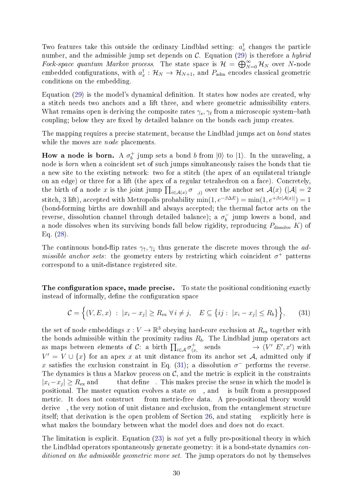
void pointing against growth, and at most 7 even counting the irregular cases. If remnants settle
in this way, a patch grown one way holds matter and no antimatter. The patch also grows as
twinned FCC, whose mirror variants coarsen into ever wider single-variant domains. The winner
is random and does not depend on any global lift orientation.
Read as a network of Bell pairs, the grown lattice obeys an exact entanglement area law,
S = ln 2 times the number of bonds crossing the boundary; one parity check per node turns it into
a code state with one qubit per bond, which lowers S by exactly ln 2 for a connected region with
a connected complement. The area-law coefficient lies 2.5–6% below that of ideal FCC because of
defects. The weight-12 FCC stabilizer code can be built on any grown graph, and its checks always
commute. About 96% of interior nodes carry its full structure (89% when all defects are counted),
0.15% of interior bonds escape every X check (1.1% counting all defects), and in patches the code
heals as twin domains coarsen.
The lift rate follows from geometry as P
lift
/P
stitch
= (2
√
2/π)δ and needs no tuning. A least-
squares unit-bond condition, the direct form of the Bell-pair rule, is needed to keep long-range
order. Each lift makes a tetrahedral unit, but the rules produce no global K = 4 stage, which
remains an assumption of the SSM. The main open question is whether remnants settle onto the
front as assumed, which a model of remnant motion could test.
Declarations
Funding
No external funding was received for this work.
Competing interests
The author is employed by IDrive Inc. and declares no other competing interests.
Data availability
The simulator (ssmsim), tests, analysis scripts, raw results (aggregated for the robustness and
lattice-check runs) and figure scripts are in one archive, ssm-growth-sim.zip, in the repository
https://github.com/raghu91302/ssmtheory. A permanent deposit with a DOI will be created
on acceptance. Two interactive views go with the paper. The growth viewer for both cases
is at https://raghu91302.github.io/ssmtheory/lattice_growth.html. The formation of a
new sheet at a step edge (Fig. 6) is at https://raghu91302.github.io/ssmtheory/step_edge_
sheet.html.
Code availability
The simulator and all analysis and figure scripts are in the same archive and repository, under the
terms stated there.
Author contributions
R.K. is the sole author and carried out all parts of the work.
30
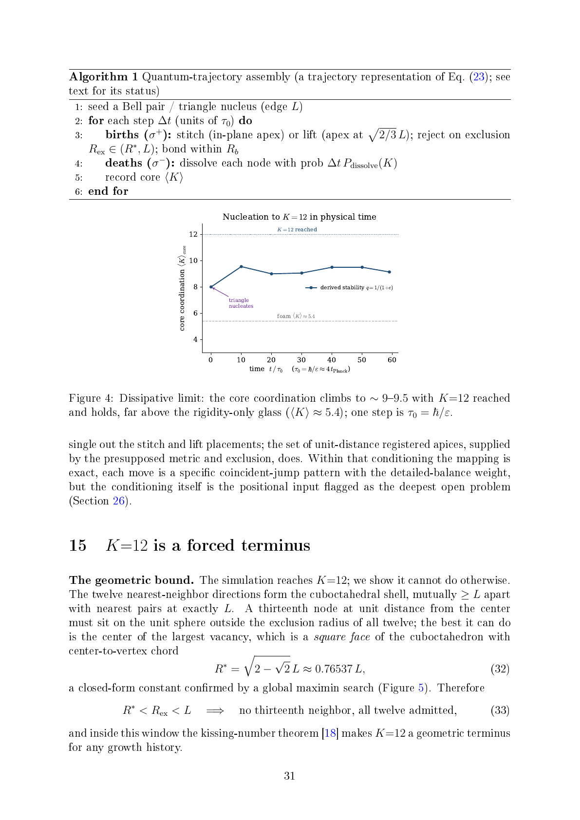
A Instability of the bare growth rule
Without the unit-bond condition, a new node’s position comes straight from its triangle, and any
error in the triangle carries over. Each node depends on several earlier nodes, so errors grow from
layer to layer. In a 32 × 32 slab, the median deviation from the ideal lattice grows from 10
−14
at layer 10 to 2 × 10
−3
at layer 100. That is a factor of about 1.3 per layer (Fig. 8). By layer
108 ± 1 it reaches the bond tolerance, and the crystal breaks into misoriented grains. This height
was the same within ±3 layers for every width and orientation tested, which showed it was an
artifact. With the unit-bond condition, the deviation stays between 10
−14
and 5 × 10
−13
through
300 layers, and slabs stay ordered through 600 layers. An earlier set of 48 slab runs without the
condition is superseded. We keep it in the archive.
0 25 50 75 100 125 150
layer
10
14
10
12
10
10
10
8
10
6
10
4
10
2
10
0
median deviation from
ideal lattice (
L
)
bond tolerance
bare rule
with unit-bond condition
Figure 8: Median deviation of node positions from the ideal lattice against layer in a 32 ×32 slab, for the
bare growth rule and with the unit-bond condition. Without the condition, rounding errors grow by about
30% per layer and reach the bond tolerance near layer 110.
B Comparison with the earlier implementation
The earlier code [2] differs in three ways. It bonds nearby nodes in batches every 40 placements.
It grows edges that belong to no triangle in a direction set by the global z axis. And it keeps a site
active until both candidate positions fail. We changed one feature at a time (N = 1,500, p = 0.05,
8 seeds; Table 18). Batched bonding explains about 9 of the 16 percentage points between the two
codes. The rest comes from site bookkeeping. The global-z rule has no measurable effect.
Table 18: Earlier implementation versus present code (N = 1,500).
Variant Bulk FCC (CNA)
Earlier code as published 0.675 ± 0.019
Bonding at every placement 0.763 ± 0.029
No global-z growth of triangle-free edges 0.671 ±0.022
Both changes 0.764 ± 0.024
Present code, legacy per-step rule (16 seeds) 0.839 ± 0.017
Present code, site-weighted rule (16 seeds) 0.883 ± 0.013
References
[1] M. Van Raamsdonk, Building up spacetime with quantum entanglement, Gen. Relativ. Gravit. 42
(2010) 2323–2329, doi:10.1007/s10714-010-1034-0.
31
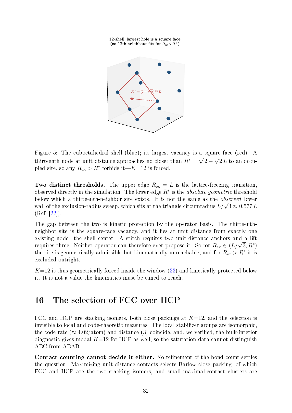
[2] R. Kulkarni, Matter as incomplete crystallization: quark charges, color confinement, and the
proton mass from a single extra node in the vacuum lattice, Physics Open 27 (2026) 100423,
doi:10.1016/j.physo.2026.100423.
[3] R. Kulkarni, The mass-energy-information equivalence: a bottom-up identification of the
particle spectrum via FCC lattice error correction, Physics Open 27 (2026) 100414,
doi:10.1016/j.physo.2026.100414.
[4] T.C. Hales, A proof of the Kepler conjecture, Ann. of Math. 162 (2005) 1065–1185,
doi:10.4007/annals.2005.162.1065.
[5] P.G. Bolhuis, D. Frenkel, S.-C. Mau, D.A. Huse, Entropy difference between crystal phases, Nature
388 (1997) 235–236, doi:10.1038/40779.
[6] P.N. Pusey, W. van Megen, P. Bartlett, B.J. Ackerson, J.G. Rarity, S.M. Underwood, Structure of crys-
tals of hard colloidal spheres, Phys. Rev. Lett. 63 (1989) 2753–2756, doi:10.1103/PhysRevLett.63.2753.
[7] R. Kulkarni, A 67%-rate CSS code on the FCC lattice: [[192, 130, 3]] from weight-12 stabilizers,
arXiv:2603.20294 [quant-ph] (2026), doi:10.48550/arXiv.2603.20294.
[8] J.A. Wheeler, Information, physics, quantum: the search for links, in: Proc. 3rd Int. Symp. Foundations
of Quantum Mechanics, Tokyo, 1989, pp. 354–368.
[9] E.P. Tryon, Is the Universe a vacuum fluctuation?, Nature 246 (1973) 396–397, doi:10.1038/246396a0.
[10] R. Kulkarni, Black holes in the FCC selection–stitch model, Eur. Phys. J. Plus 141 (2026) 916,
doi:10.1140/epjp/s13360-026-08148-9.
[11] W.H. Zurek, Quantum Darwinism, Nature Phys. 5 (2009) 181–188, doi:10.1038/nphys1202.
[12] D. Deutsch, C. Marletto, Constructor theory of information, Proc. R. Soc. A 471 (2015) 20140540,
doi:10.1098/rspa.2014.0540.
[13] B. Swingle, Entanglement renormalization and holography, Phys. Rev. D 86 (2012) 065007,
doi:10.1103/PhysRevD.86.065007.
[14] C. Cao, S.M. Carroll, S. Michalakis, Space from Hilbert space: recovering geometry from bulk entan-
glement, Phys. Rev. D 95 (2017) 024031, doi:10.1103/PhysRevD.95.024031.
[15] J. Barrett, Information processing in generalized probabilistic theories, Phys. Rev. A 75 (2007) 032304,
doi:10.1103/PhysRevA.75.032304.
[16] V. Coffman, J. Kundu, W.K. Wootters, Distributed entanglement, Phys. Rev. A 61 (2000) 052306,
doi:10.1103/PhysRevA.61.052306.
[17] B.M. Terhal, Is entanglement monogamous?, IBM J. Res. Dev. 48 (2004) 71–78,
doi:10.1147/rd.481.0071.
[18] H. Barnum, C.M. Caves, C.A. Fuchs, R. Jozsa, B. Schumacher, Noncommuting mixed states cannot
be broadcast, Phys. Rev. Lett. 76 (1996) 2818–2821, doi:10.1103/PhysRevLett.76.2818.
[19] S. Popescu, D. Rohrlich, Quantum nonlocality as an axiom, Found. Phys. 24 (1994) 379–385,
doi:10.1007/BF02058098.
[20] D. Gross, M. M¨uller, R. Colbeck, O.C.O. Dahlsten, All reversible dynamics in maximally nonlocal
theories are trivial, Phys. Rev. Lett. 104 (2010) 080402, doi:10.1103/PhysRevLett.104.080402.
[21] L. Hardy, Quantum theory from five reasonable axioms (2001), arXiv:quant-ph/0101012.
[22] G. Chiribella, G.M. D’Ariano, P. Perinotti, Informational derivation of quantum theory, Phys. Rev. A
84 (2011) 012311, doi:10.1103/PhysRevA.84.012311.
[23] L. Masanes, M.P. M¨uller, A derivation of quantum theory from physical requirements, New J. Phys.
13 (2011) 063001, doi:10.1088/1367-2630/13/6/063001.
32
[24] M. Pl´avala, General probabilistic theories: an introduction, Phys. Rep. 1033 (2023) 1–64,
doi:10.1016/j.physrep.2023.09.001.
[25] M.-O. Renou et al., Quantum theory based on real numbers can be experimentally falsified, Nature
600 (2021) 625–629, doi:10.1038/s41586-021-04160-4.
[26] M.-C. Chen et al., Ruling out real-valued standard formalism of quantum theory, Phys. Rev. Lett. 128
(2022) 040403, doi:10.1103/PhysRevLett.128.040403.
[27] U. Sinha, C. Couteau, T. Jennewein, R. Laflamme, G. Weihs, Ruling out multi-order interference in
quantum mechanics, Science 329 (2010) 418–421, doi:10.1126/science.1190545.
[28] D.N. Page, W.K. Wootters, Evolution without evolution: dynamics described by stationary observ-
ables, Phys. Rev. D 27 (1983) 2885–2892, doi:10.1103/PhysRevD.27.2885.
[29] E. Moreva, G. Brida, M. Gramegna, V. Giovannetti, L. Maccone, M. Genovese, Time
from quantum entanglement: an experimental illustration, Phys. Rev. A 89 (2014) 052122,
doi:10.1103/PhysRevA.89.052122.
[30] E.H. Lieb, D.W. Robinson, The finite group velocity of quantum spin systems, Commun. Math. Phys.
28 (1972) 251–257, doi:10.1007/BF01645779.
[31] S. Popescu, A.J. Short, A. Winter, Entanglement and the foundations of statistical mechanics, Nature
Phys. 2 (2006) 754–758, doi:10.1038/nphys444.
[32] T. Regge, General relativity without coordinates, Il Nuovo Cimento 19 (1961) 558–571,
doi:10.1007/BF02733251.
[33] S.K. Lam, A. Pitrou, S. Seibert, Numba: a LLVM-based Python JIT compiler, in: Proc. Second
Workshop on the LLVM Compiler Infrastructure in HPC (LLVM-HPC 2015), ACM, 2015, article 7,
doi:10.1145/2833157.2833162.
[34] J.D. Honeycutt, H.C. Andersen, Molecular dynamics study of melting and freezing of small Lennard-
Jones clusters, J. Phys. Chem. 91 (1987) 4950–4963, doi:10.1021/j100303a014.
[35] D. Faken, H. J´onsson, Systematic analysis of local atomic structure combined with 3D computer
graphics, Comput. Mater. Sci. 2 (1994) 279–286, doi:10.1016/0927-0256(94)90109-0.
[36] A. van der Drift, Evolutionary selection, a principle governing growth orientation in vapour-deposited
layers, Philips Res. Rep. 22 (1967) 267–288.
[37] A.R. Calderbank, P.W. Shor, Good quantum error-correcting codes exist, Phys. Rev. A 54 (1996)
1098–1105, doi:10.1103/PhysRevA.54.1098.
[38] A.M. Steane, Error correcting codes in quantum theory, Phys. Rev. Lett. 77 (1996) 793–797,
doi:10.1103/PhysRevLett.77.793.
[39] D. Gottesman, Stabilizer codes and quantum error correction, PhD thesis, California Institute of
Technology (1997), arXiv:quant-ph/9705052.
[40] J. Eisert, M. Cramer, M.B. Plenio, Colloquium: Area laws for the entanglement entropy, Rev. Mod.
Phys. 82 (2010) 277–306, doi:10.1103/RevModPhys.82.277.
[41] A. Kitaev, J. Preskill, Topological entanglement entropy, Phys. Rev. Lett. 96 (2006) 110404,
doi:10.1103/PhysRevLett.96.110404.
[42] M. Levin, X.-G. Wen, Detecting topological order in a ground state wave function, Phys. Rev. Lett.
96 (2006) 110405, doi:10.1103/PhysRevLett.96.110405.
[43] A.Yu. Kitaev, Fault-tolerant quantum computation by anyons, Ann. Phys. 303 (2003) 2–30,
doi:10.1016/S0003-4916(02)00018-0.
[44] C.H. Bennett, Serially deposited amorphous aggregates of hard spheres, J. Appl. Phys. 43 (1972)
2727–2734, doi:10.1063/1.1661585.
33